- Science Toys
- Magnetism
- Electromagnetism
- Electrochemistry
- Radio
- Thermodynamics
- Aerodynamics
- Light and optics
- Simple laser communicator
- Make your own 3D pictures
- Making permanent rainbows.
- A solar powered marshmallow roaster
- Make a spectroscope from a CD.
- The impossible kaleidoscope
- Make a solar hotdog cooker
- Exploring invisible light
- A high resolution spectrograph.
- Time-lapse photography.
- High speed photography.
- Stacking photos for high depth of field.
- Biology
- Mathematics
- Computers and Electronics
A simple laser communicator.
How would you like to talk over a laser beam? In about 15 minutes you can set up your own laser communication system, using cheap laser pen pointers and a few parts from Radio Shack. For the transmitter you will need:- A laser pen pointer. You can get one for $10 from our catalog.
- A battery holder that holds the same number of batteries as the laser pointer (often 3 cells). The batteries can be any size, but they must be the same voltage as the laser batteries. You may need to get one that holds two cells, and another that holds one cell, and wire them together in series. Radio Shack has a decent selection.
- A transistor radio. Later we will use a microphone and an amplifier (Radio Shack #33-1067 and #277-1008), but at first we will send your favorite radio station over the laser beam.
- An earphone jack that will fit your transistor radio (Radio Shack #42-2434).
- A transformer of the type known as an audio output transformer. It consists of an 8 ohm coil and a 1000 ohm coil. The one I used is the Radio Shack #273-1380. We now carry them in our catalog.
- Some clip leads (wires with alligator clips on the ends) to put it all together. At least one of the clip leads should be the type with a long slender point (Radio Shack #278-016, #270-372, or #270-334), to connect to the inside of the laser pointer. You can substitute regular wire and solder if you like, but the clip leads are fast and simple. Radio Shack has a wide selection of clip leads (such as ##270-378).
- A two-lead bicolor light emitting diode, to protect the laser from high voltage spikes.
- A small solar cell (such as Radio Shack #276-124). You may have to solder your own wires to it if it doesn't come with wires attached.
- A microphone jack that will fit the phono input of your stereo (Radio Shack #42-2434 or ##42-2457). Instead of a stereo, you can use the small amplifiers that Radio Shack sells (#277-1008).
Setup and testing
Make sure the transistor radio is turned off, and the laser is on. Plug the earphone jack of the laser into the earphone socket of the radio. Connect the solar cell to the amplifier or stereo, and turn the volume up until you hear a hissing noise, then turn it down slightly until the hiss isn't noticeable. The volume control should be fairly high, corresponding to an ear splitting level if it was playing music. Aim the laser across the room so it hits the solar cell. You might hear clicks or pops coming from the stereo or amplifier as the laser beam passes over the solar cell. This indicates that everything is working fine at this point.Click on photo for larger picture Now carefully turn on the radio and slowly adjust the volume until you hear the radio station voices or music coming from the amplifier across the room. The radio should be just audible if the earphone jack is pulled out, not loud. If you can't hear the sound from the amplifier across the room, make sure the laser is shining on the solar cell, then try increasing the volume of the amplifier before you increase the volume of the radio. At this point you should be hearing the radio station coming in loud and clear in the amplifier across the room. Put your hand in front of the laser beam to break the connection, and notice that the music stops. Wiggle your fingers in the beam and listen to the music get chopped up by your fingers. Your laser communicator is ready for the next step. To send your voice over the laser beam, you simply replace the transistor radio with a microphone and amplifier. Radio Shack sells small amplifiers (about the same size as the transistor radio) that have sockets for microphones and earphones. You can also use another stereo system, but be very careful with the volume control to prevent damage to the laser.
Using a disassembled laser pointer.
For this project we have removed the laser assembly from a small $10.00 laser pointer. The power supply circuit is the green board attached to the brass laser head. We carry similar laser pointers in our catalog that are easily disassembled for this project. The laser below has voltage spike protection on the circuit board. The one you get may not have this, and so you will want to put a bicolor LED across the transformer like we did in the previous version. The power supply circuit came conveniently marked with a plus and
a minus next to two holes in the board. We solder the black negative
lead from the battery clip to the hole marked minus. We solder one of
the 1000 ohm coil leads to the hole marked plus. We solder the red
positive lead of the battery clip to the other lead from the 1000 ohm
coil.
The power supply circuit came conveniently marked with a plus and
a minus next to two holes in the board. We solder the black negative
lead from the battery clip to the hole marked minus. We solder one of
the 1000 ohm coil leads to the hole marked plus. We solder the red
positive lead of the battery clip to the other lead from the 1000 ohm
coil.
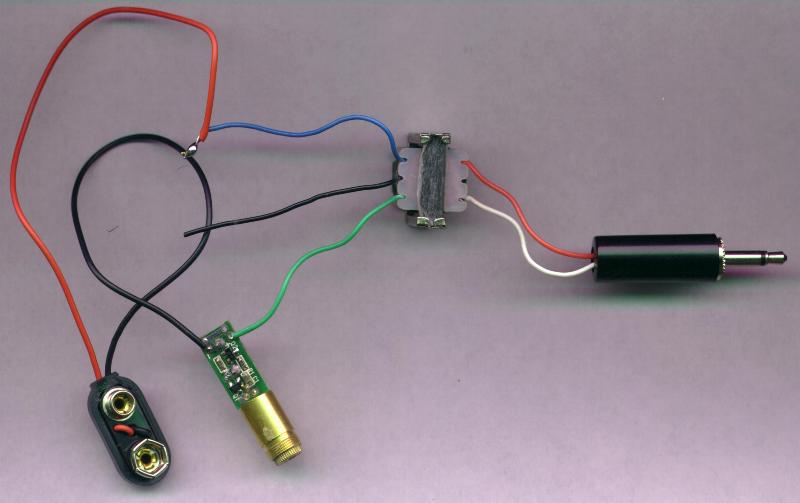 The battery clip is attached to a 4.5 volt battery pack (not
a 9 volt battery!). Since I didn't have a pack that takes 3 cells,
I used one that takes 4 AA batteries, and I replaced one of the four
batteries with a straight piece of bare wire.
That's it! We have a laser transmitter, in just a few minutes!
The battery clip is attached to a 4.5 volt battery pack (not
a 9 volt battery!). Since I didn't have a pack that takes 3 cells,
I used one that takes 4 AA batteries, and I replaced one of the four
batteries with a straight piece of bare wire.
That's it! We have a laser transmitter, in just a few minutes!
A new receiver
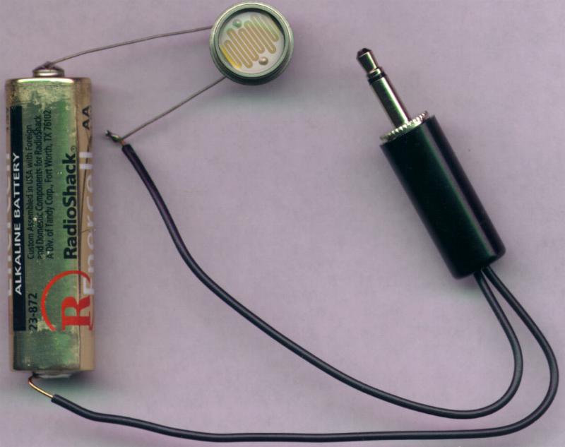
The solar cell receiver has some drawbacks. It is expensive (solar cells are a few dollars each), and fragile. A cheaper, sturdier alternative is to use a cadmium sulphide photoresistor instead of the silicon photocell. A cadmium sulphide photoresistor is shown below (magnified many times). It does not produce electricity from light the way the solar cell did. Instead, the light that falls on it changes its resistance to electricity. If we connect a battery and a photoresistor together, they can act like the solar cell. As the intensity of the light changes, the amount of electricity output changes in response.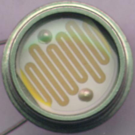 The new receiver is very simple, and looks like this:
Super simple receivers
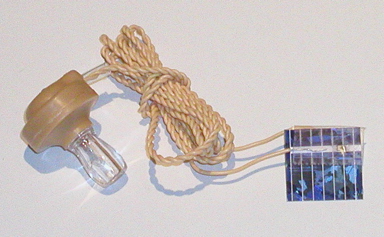
Using a super sensitive piezoelectric earphone (see our catalog), you can make a laser voice receiver that doesn't need any expensive amplifiers or power source. Just connect it to a small solar cell, as shown below: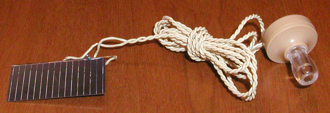
Click on photo for larger picture Also in our catalog, we have tiny silicon solar cells that you can attach to a piezoelectric earphone with simple transparent tape, instead of soldering (which can be difficult to do on silicon solar cells).
Click on photo for larger picture If a solar cell is too expensive or fragile, a cadmium-sulfide photoresistor can also be used. The earphone wires are connected across the photoresistor, and the battery is also connected across the same wires. The battery, the earphone, and the photoresistor are in parallel. A 220 ohm resistor is placed in series with the battery, to reduce power consumption, and prevent heating of the photoresistor.
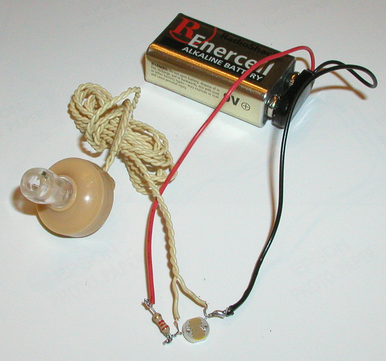
Click on photo for larger picture Either of these earphone approaches has the nice feature of making the communication private. Only you can hear what is coming over the secret laser link.
How does it do that?
In all of the laser communicators on this page, the laser light is amplitude modulated. This simply means that the amount of light the laser emits varies over time. To understand what is going on, it helps to consider how a loudspeaker makes sound. A loudspeaker is a paper cone attached to a coil of wire that sits in a magnetic field from a strong permanent magnet. When an electric current flows in the loudspeaker coil, the coil becomes an electromagnet, and it moves toward or away from the permanent magnet. As it moves, the paper cone pushes on the air around it, compressing the air in front of it, and expanding the air behind it. Waves of compressed and expanded air travel to your ear, and cause your eardrum to move in time to the movements of the paper cone. The laser communicator adds two components to the loudspeaker concept. We take the electrical signal that goes to the loudspeaker, and connect it instead to the laser, so the laser gets brighter and dimmer as the electric current varies. The second component is the receiver, which converts the light back into an electric current. This current varies in time with the first current, because the amount of light that it receives is varying in time. This second electric current is used to move the paper cone of a loudspeaker, just as before. However, now the loudspeaker can be quite a distance away from the original electric current, without any wires connecting the two.Make your own 3D pictures in minutes
In this section you will see just how easy it is to take pictures that show realistic three dimensional (3D) images. The pictures can be viewed in three ways: by crossing your eyes, by focussing you eyes at infinity (called the 'parallel' method because the two lines of sight are parallel), and with an inexpensive (or homemade) 3D viewer. The viewer is nice because it takes a little practise to see the images with the first two methods, and most people find the viewer easier and more comfortable.Taking the pictures
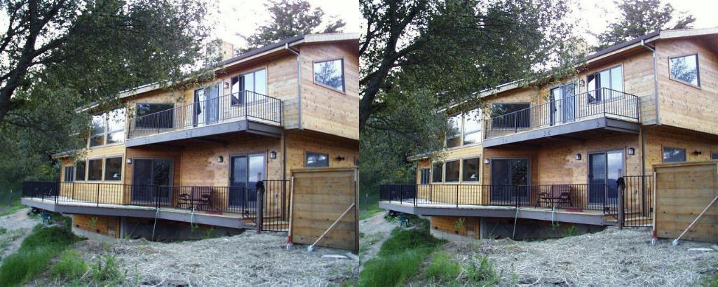
This is actually the simplest part. You can use any camera you have available. Just take a picture, then move the camera to the side a little bit, then take another picture. That's all there is to it. I like to use a tripod, but some people just shift their balance from one foot to the other for each shot. The next step is to place the two pictures next to one another and cross your eyes to see the 3D view. For cross-eyed viewing, the picture that was taken from the right side goes on the left, and the picture taken from the left side goes on the right. If you have an instant camera, the pictures (of course) can be viewed right away. I like to use a digital camera, because the pictures are higher quality, and I can still see them right away on the screen. Even if you use a standard film camera, the pictures can be digitized on a scanner (either at home or through the services of your film processing company) and then pasted together to be viewed on the screen or printed on a color printer. To view cross-eyed, keep the pictures at a distance where you can comfortably focus on them. Slowly cross your eyes until instead of two pictures, you see three. The center picture will be in 3D. It takes some practice. If you find yourself straining your eye muscles, you may be trying to focus on the air between you and the pictures, where your eyes are aiming. Relax, and try again, letting your eyes focus on the pictures, but cross so the left eye sees the right picture, and the right eye sees the left. Once you get the hang of it, you can do it comfortably right away, and can view the pictures as long as you like, shifting your gaze from items in the foreground to items in the background effortlessly. The 3D effect is stunning, not only because of the stereo effect, but because there is twice as much information getting to your brain. It is almost like being there. In the pictures below, start with the smallest ones, and only go on to the larger versions when you can comfortably get the 3D effect. Sometimes it helps to start farther away, and move closer only when your eyes are properly positioned and you can see the 3D effect.Cross your eyes to view these images in stereo 3D

My house
640
800
1024
1280

A path to the treehouse
640
800
1024
1280

The view from my home office window
640
800
1024
1280
Some people find it easier to aim their eyes at infinity rather than
to cross them. Because two light rays coming from infinity are parallel
when they reach your eyes, this method is called the 'parallel' method.
The problem with the parallel method is that the pictures must be the
width of the distance between your eyes. That's not very big, and that
limits the detail you can get on a computer monitor. It is less of a
problem with photographic prints (since they contain a lot more detail
per square inch than a computer monitor).
For parallel viewing, the pictures are reversed from cross-eyed viewing.
The picture taken from the right is on the right, and is viewed by the
right eye.
In the photos below, find the size that makes the pictures on your
monitor close in width to the distance between your eyes. Then relax,
and let your eyes drift through the pictures as if they were viewing
a mountaintop far in the distance. You will gradually be able to see
three pictures as with the cross-eyed method, and like then, the center
picture will be in 3D.
For me, it sometimes helps to get very close to the screen, so the
pictures are very blurry. This makes it so that each eye is very
definitely looking at a different picture. Then, when I have a blurry
3D image, I slowly back away from the screen until it comes in focus,
being careful not to lose the 3D sensation. When you are very close
to the screen, it will look like the two pictures have merged into
one. As you back away, you will be able to see the other two pictures
flanking the 3D center image.
View these pictures with eyes parallel (looking at infinity)

My house
640
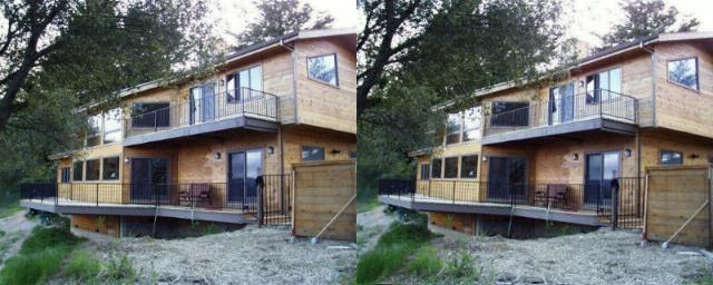

A path to the treehouse
640

The view from my home office window
640
All of these photos so far have been done with the 'hyper-stereo'
technique, where the camera positions are separated by more than
the distance between the eyes. For true stereo, try holding your
head completely still (rest it against a wall for example), and
hold the camera up to one eye for the first shot, then up to the
other eye for the second shot. These 3D images will work well for
objects that are nearby, and will not give the exagerated 3D for
distant objects that you see in the images of the lake in the
photos above.
For very close-up objects, you can move the camera by less than
the distance between your eyes. Now, instead of seing the 3D
effect behind the plane of the picture, the image seems to float
in mid-air between you and the screen or paper. For this to
work well, you may need a special close-up lens on your camera.
However, sometimes just shooting the picture with a magnifying
glass taped over the camera sun shade will give very good results.
If you do want to play with the hyper-stereo effect, remember that
the brain finds it easiest to see 3D images if the distance from the
camera to the object is 30 times the distance between to two camera
positions. If an object is 30 feet away, the camera position for the
second shot should not be more than 1 foot from the position of the
first shot.
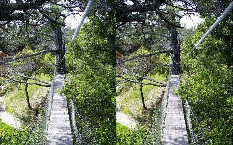
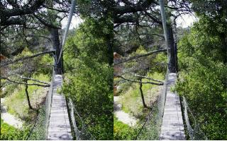
The pictures below are done in true stereo, holding the camera first
to one eye, then to the other. The subject is the treehouse bridge
between two trees in my yard. It is 70 feet long and 45 feet above
the ground. You can see a little bit of my house in the background
in one of the pictures.
Cross your eyes to view these images in stereo 3D

The treehouse bridge
640
800
1024
1280

The treehouse bridge from the other side
640
800
1024
1280
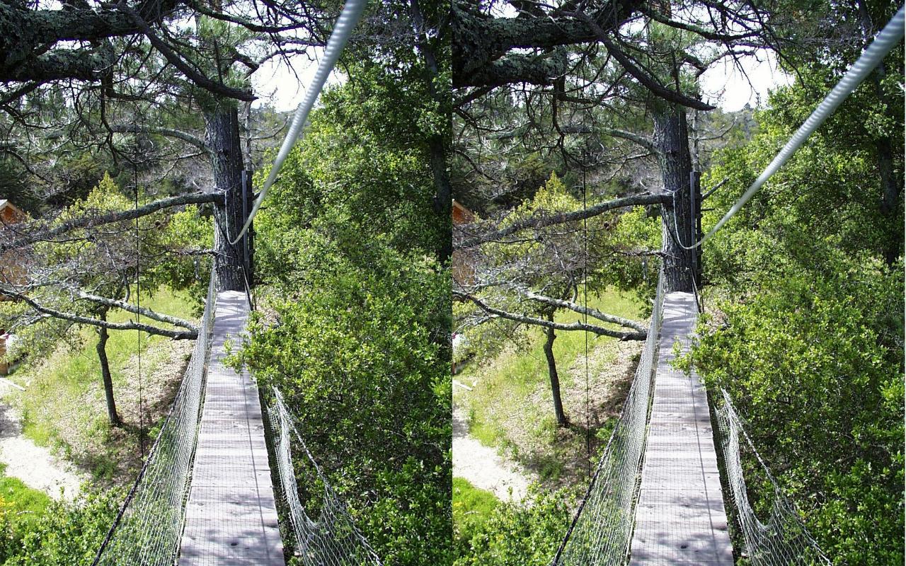
View these pictures with eyes parallel (looking at infinity)
The treehouse bridge
640
800
1024
1280

The treehouse bridge from the other side
640
800
1024
1280
Remember, for the parallel viewing, each half of the picture must
be about as wide as the distance between your eyes. A little smaller
is usually OK, but bigger won't work. I am including some big images
just in case you have a remarkable computer monitor, or you wish to
print the pictures out and view them with a viewer.
Using a viewer to see the pictures
There is an inexpensive viewer available from a company called 3DViewMax that makes viewing these images very easy and comfortable. They will send you the viewer by first class mail, so it may arrive as soon as the next day. The viewer is a simple pair of plastic prisms (with a bit of magnification also) in a folding cardboard holder that keeps the pictures at the proper distance. The prisms make it easier for your eyes to view parallel format stereograms. You can use the viewer to view pictures directly from the computer screen, or you can place your own pictures next to one another in the viewer. I print out mine on a good color printer on premium paper. The trick is simply to tell the printer to print the stereogram so it is 6 inches wide. This is because the 3-D ViewMax viewer is designed for 6 inch pictures. If you are having your own photographs printed for you, have them printed 3 inches wide, so the stereogram will be 6 inches wide when they are side by side. It is a little difficult to build this kind of viewer yourself. The magnification is not strictly necessary, so the viewer can be made by putting a small wedge prism in front of each eye. These prisms can be made by sanding and polishing small pieces of clear plastic, but this takes some skill. Another way to make a viewer is with small circular mirrors. The mirrors are oriented 90 degrees from each other, and separated by the same distance as your eyes. When you look into the mirrors, the left eye will be looking left, and the right eye will be looking right. The pictures are not stuck together in this viewer, but are placed near the operator's shoulders, the left view on the left, and the right view on the right. Such a viewer is more cumbersome to use than the 3-D ViewMax, but it is easier to explain to a younger child how it works, and being home-made, it might make a better science fair project. For more information on light and optics, see the Recommended Reading section. Next: Making permanent rainbows Order laser communicator kits and parts here. Del.icio.us- Science Toys
- Magnetism
- Electromagnetism
- Electrochemistry
- Radio
- Thermodynamics
- Aerodynamics
- Light and optics
- Simple laser communicator
- Make your own 3D pictures
- Making permanent rainbows.
- A solar powered marshmallow roaster
- Make a spectroscope from a CD.
- The impossible kaleidoscope
- Make a solar hotdog cooker
- Exploring invisible light
- A high resolution spectrograph.
- Time-lapse photography.
- High speed photography.
- Stacking photos for high depth of field.
- Biology
- Mathematics
- Computers and Electronics
Some of my other web sites:

Send mail to Simon Quellen Field via [email protected]