- Science Toys
- Magnetism
- Electromagnetism
- Electrochemistry
- Radio
- Thermodynamics
- Aerodynamics
- Light and optics
- Simple laser communicator
- Make your own 3D pictures
- Making permanent rainbows.
- A solar powered marshmallow roaster
- Make a spectroscope from a CD.
- The impossible kaleidoscope
- Make a solar hotdog cooker
- Exploring invisible light
- A high resolution spectrograph.
- Time-lapse photography.
- High speed photography.
- Stacking photos for high depth of field.
- Biology
- Mathematics
- Computers and Electronics
A simple 1 watt audio amplifier
The solderless breadboard makes it easy to experiment with additions to the radio circuit. In this section, we will build a simple amplifier, so that a whole room can hear the radio through a speaker. Our amplifier will not be ear shattering, since we have made it as simple as we can to build, but the output is pretty impressive for a single transistor.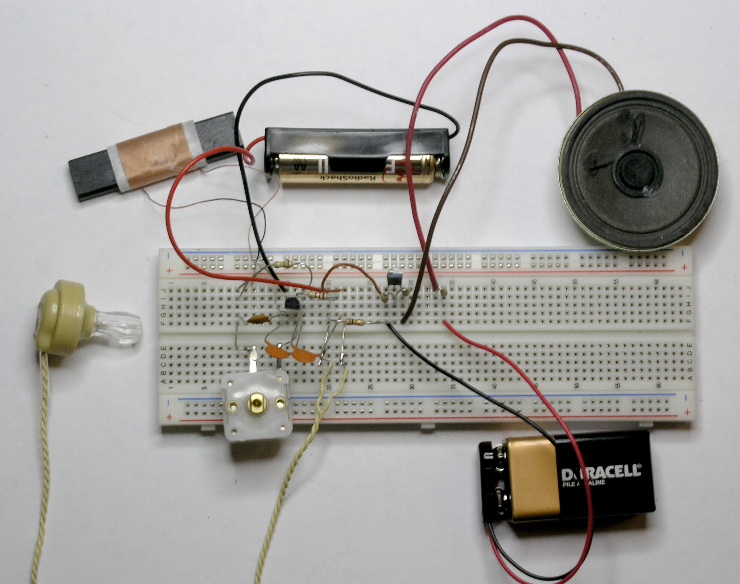
Click on photo for a larger picture
With the amplifier, our radio looks like the photo above. Below is a closeup of the amplifier section:

Click on photo for a larger picture
We carry all the parts for the amplifier (except the battery) in our catalog. The amplifier needs these parts:
- An MPSW45A Darlington transistor
This is the main working part of the amplifier. - A small speaker
- Two 100,000 ohm resistors
This resistor will have four colored bands on it. The colors will be brown, black, yellow, and gold. - A 10,000 ohm resistor
The colors will be brown, black, orange, and gold. - A 50 ohm resistor
The colors will be green, black, black, and gold. - A 9 volt battery clip
- A 9 volt battery
- Jumper wire: J22 to I27
- 10,000 ohm resistor( brown, black, orange): G20 to F28
- 100,000 ohm resistor( brown, black, yellow): H27 to H28
- 100,000 ohm resistor( brown, black, yellow): I28 to I29
- MPSW45A: J27, J28, and J29
- 50 ohm resistor( green, black, black): I33 to I34
- Speaker: F29 to J33
- Negative 9 volt battery wire (black): F26
- Positive 9 volt battery wire (red): F34
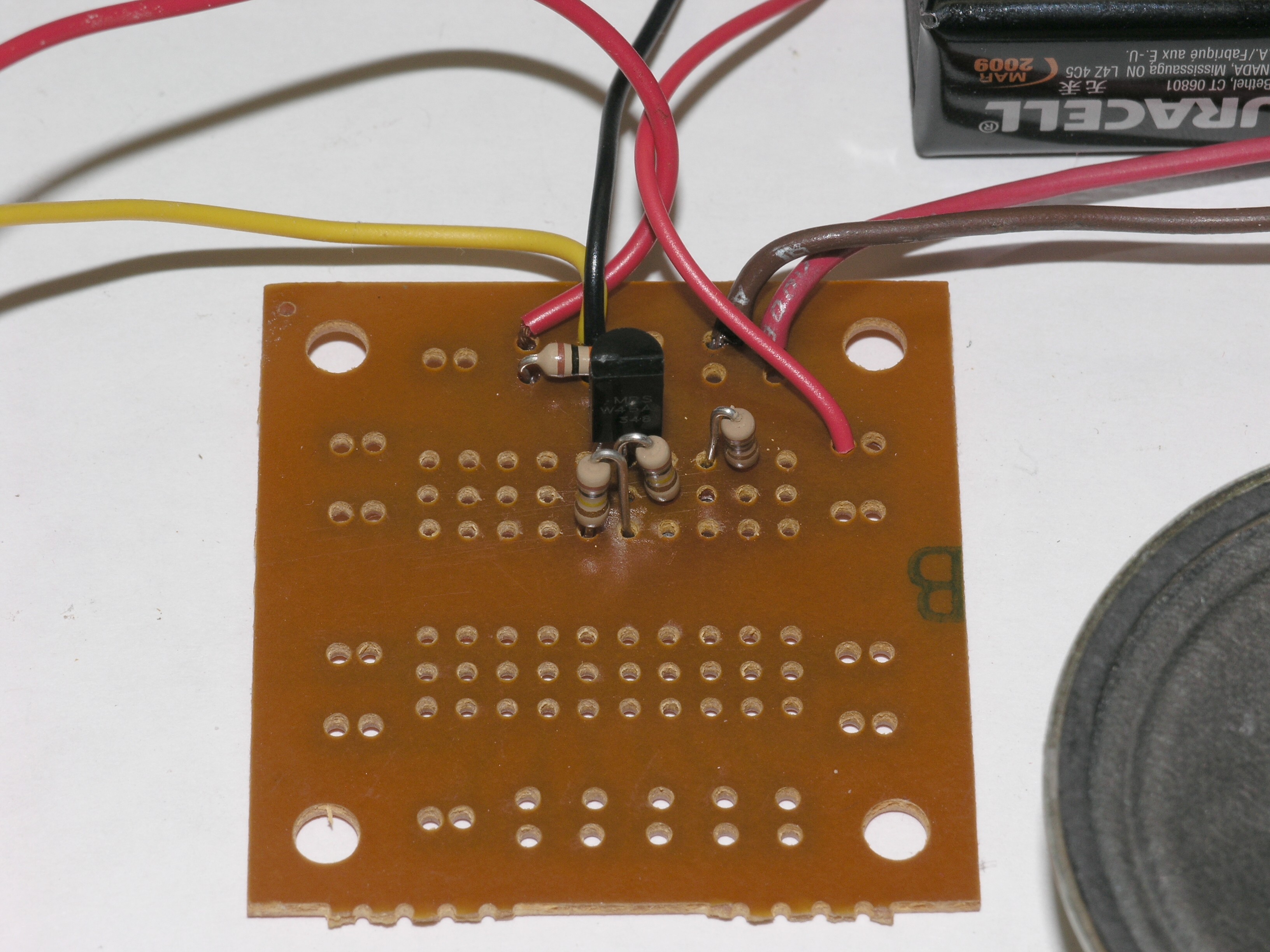
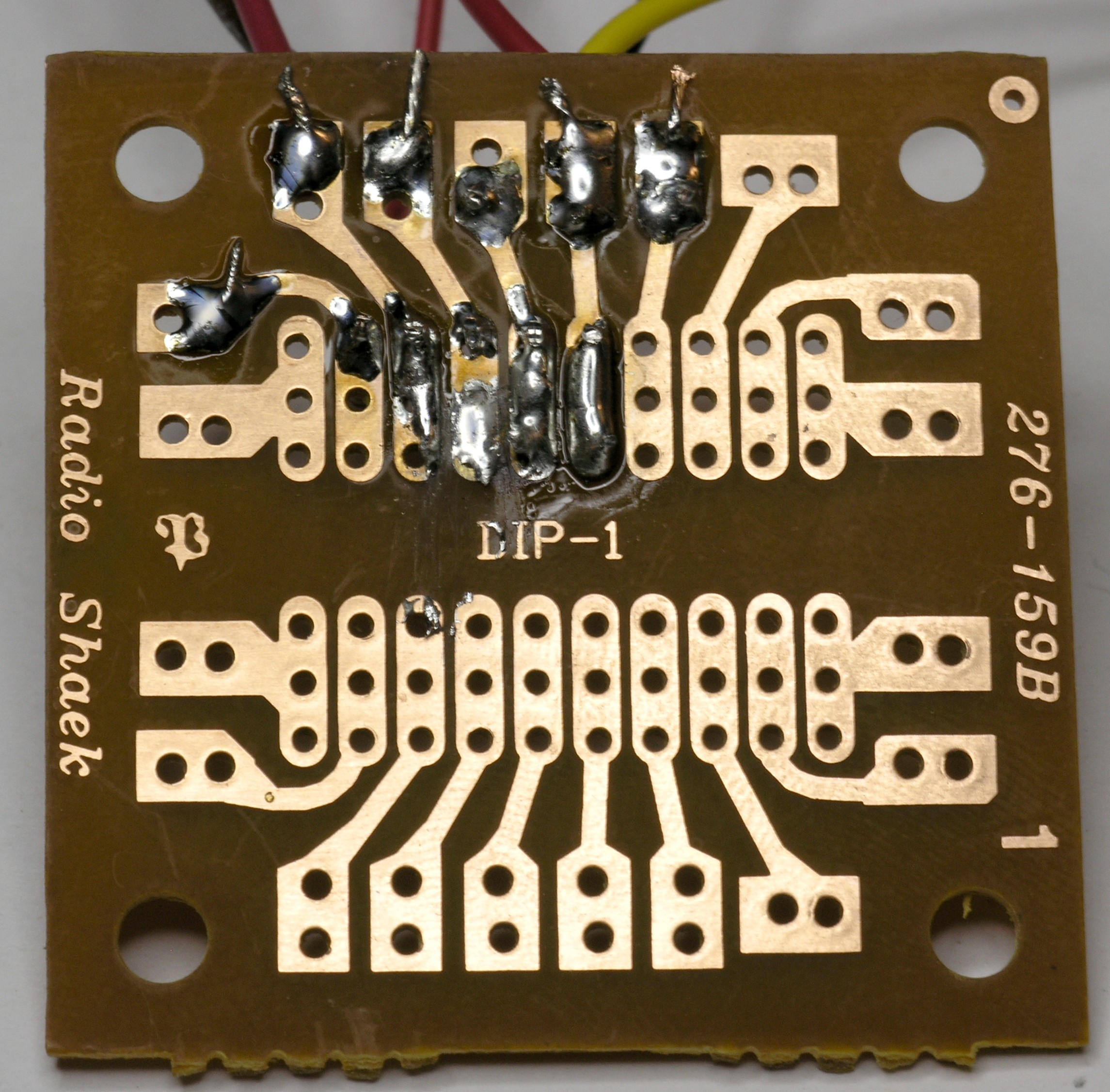
A more permanent version
As before, we can copy the circuit onto a printed circuit board and solder all of the parts firmly in place.
Click on photo for a larger picture
Click on photo for a larger picture
Click on photo for a larger picture
How does it do that?
The heart of the amplifier is the transistor. We could have used a more ordinary NPN transistor, such as the 2N4401, but to get a louder sound, we use a special "two-in-one" type of transistor called a Darlington.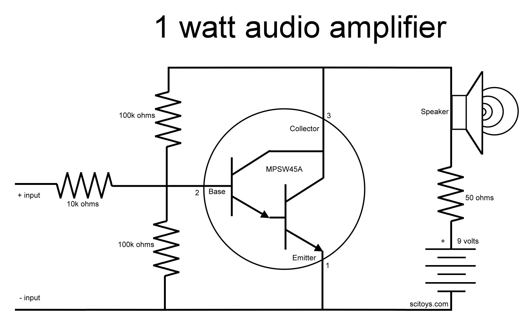
Click on photo for a larger picture
The Darlington transistor has two transistors in the same package, and can amplify signals much more than a single transistor can. Transistors amplify a signal by acting like a variable resistor. We put the signal in at the base, and the signal controls how much current goes through the transistor from the emitter to the collector. If we simply put the signal into the base, however, the transistor would turn off completely when the signal was low, and turn on completely when the signal is high. This behavior is useful when we want to use the transistor as a switch, but we have to change the behavior to make a good audio amplifier. When the signal is at zero, we want the output of the amplifier to be halfway between 0 and 9 volts (4.5 volts). We can arrange for this to happen by using a voltage divider. A voltage divider is two resistors, one connected to the positive side of the battery, and the other to the negative side. Where they meet in the middle, the voltage will be divided in half (if the resistors are the same). Since current flows through the resistors all the time, we want their values to be high, so that not much current flows through them. This will prevent them from getting hot, and make the battery last longer. In our circuit we use 100,000 ohms. Large resistors in the voltage divider also make it easier for the signal to push the voltage higher or lower. This is a good thing, since it means our amplifier will be more sensitive. In our case, the signal from the radio is a little too strong, and the signal pushes the voltage too high and too low, causing distortion. So, we add another resistor, with 10,000 ohms, to match the signal to our amplifier. The transistor can handle 1 watt before it gets too hot, reducing its lifetime. If we let the full 9 volts get in, the circuit would draw over 2 watts, and while the sound would be nice and loud, the transistor would get quite hot, and the battery would not last long. To make the amplifier draw only one watt, we put in a 50 ohm resistor to lower the current. You may have noticed in the photos that I actually used 100 ohms for the prototype, to keep the noise level down in the lab. You can think of this resistor as a volume control, although you can't adjust it without picking another resistor. A variable resistor that can handle 2 watts and went from 50 ohms to 150 ohms would let you vary the volume. We will leave that modification to the experimenter. Next: A 1 watt integrated circuit audio amplifier. Del.icio.us
- Science Toys
- Magnetism
- Electromagnetism
- Electrochemistry
- Radio
- Thermodynamics
- Aerodynamics
- Light and optics
- Simple laser communicator
- Make your own 3D pictures
- Making permanent rainbows.
- A solar powered marshmallow roaster
- Make a spectroscope from a CD.
- The impossible kaleidoscope
- Make a solar hotdog cooker
- Exploring invisible light
- A high resolution spectrograph.
- Time-lapse photography.
- High speed photography.
- Stacking photos for high depth of field.
- Biology
- Mathematics
- Computers and Electronics
Some of my other web sites:

Send mail to Simon Quellen Field via [email protected]