- Science Toys
- Magnetism
- Electromagnetism
- Electrochemistry
- Radio
- Thermodynamics
- Aerodynamics
- Light and optics
- Simple laser communicator
- Make your own 3D pictures
- Making permanent rainbows.
- A solar powered marshmallow roaster
- Make a spectroscope from a CD.
- The impossible kaleidoscope
- Make a solar hotdog cooker
- Exploring invisible light
- A high resolution spectrograph.
- Time-lapse photography.
- High speed photography.
- Stacking photos for high depth of field.
- Biology
- Mathematics
- Computers and Electronics
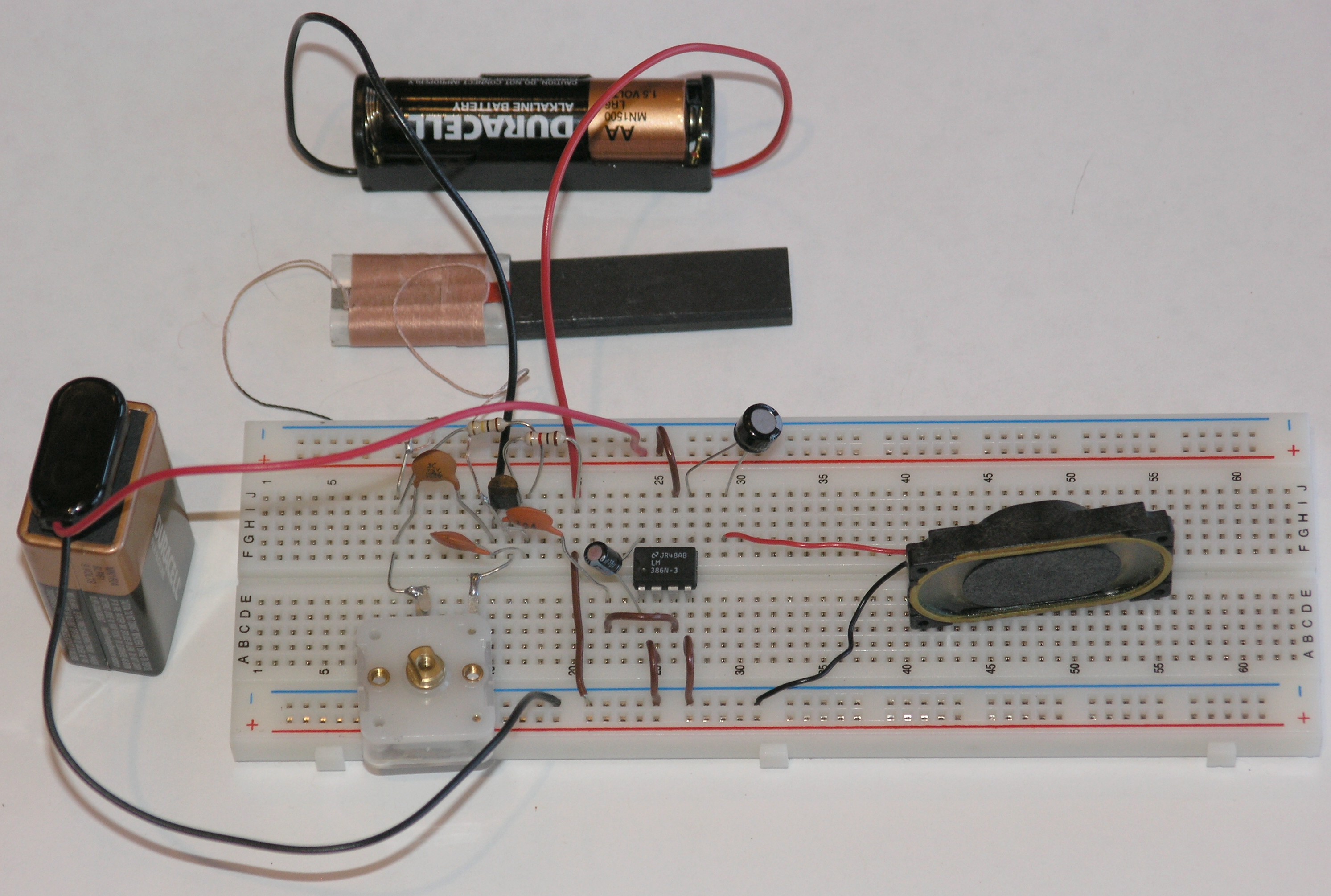
An integrated circuit audio amplifier
Like the simple amplifier in the previous section, this project starts with the solderless breadboard version of our Three Penny Radio, and adds an amplifier. But this amplifier has several important improvements over the simple one transistor amplifier. This project uses an integrated circuit with 10 transistors to amplify much better with much less power drain on the batteries than our simple amplifier.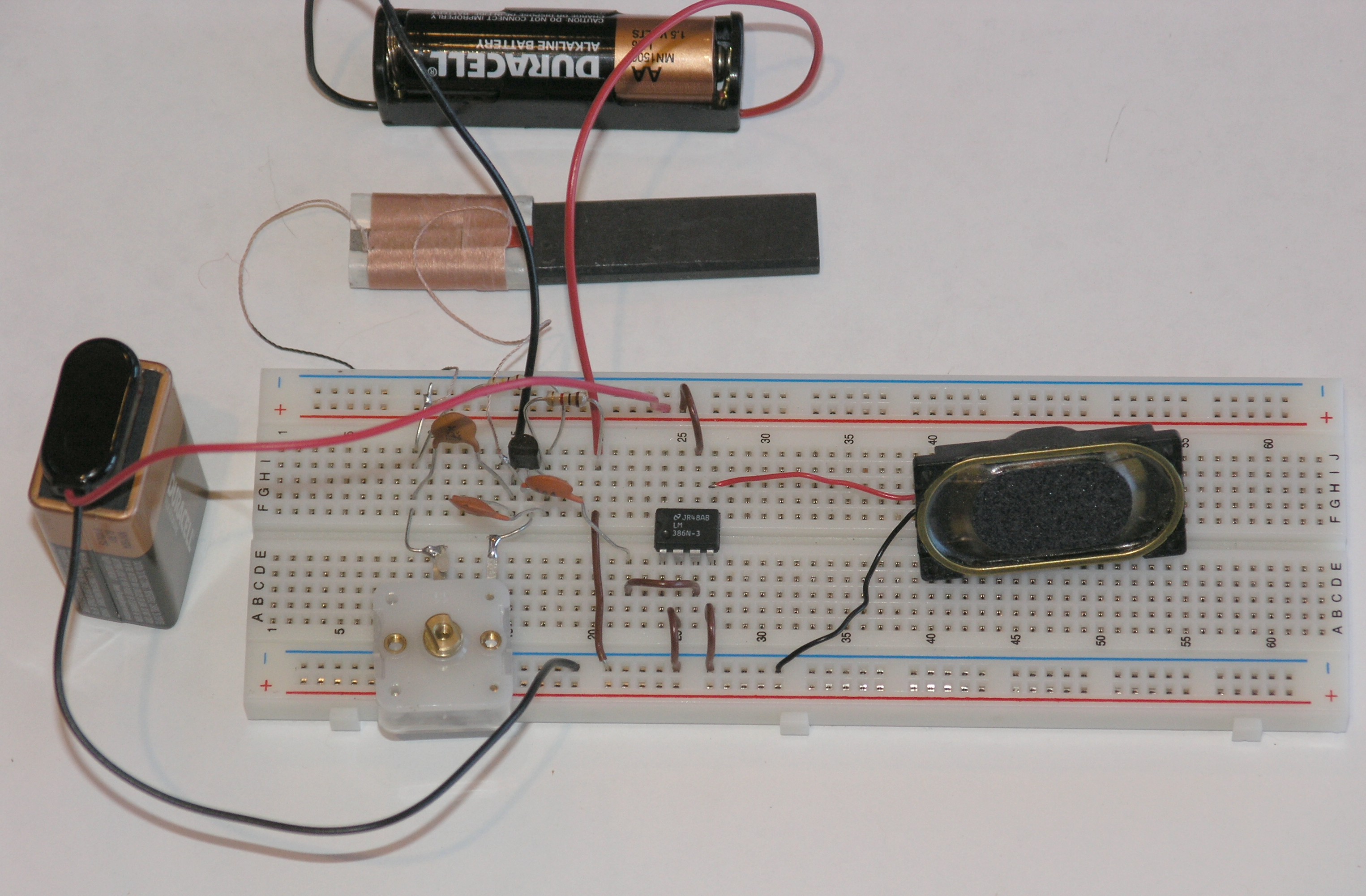 Click on photo for a larger picture
The amplifier needs these parts:
- An LM386 integrated circuit amplifier chip
This is the main working part of the amplifier. - A small speaker
- Some jumper wires
- A 9 volt battery clip
- A 9 volt battery
- A 10 microfarad capacitor
- A 220 microfarad capacitor
- A 0.033 microfarad capacitor
- A 0.047 microfarad capacitor
- A 10 ohm resistor
The colors will be brown, black, black, and gold. - A 10,000 ohm resistor
The colors will be brown, black, orange, and gold. - A 1,200 ohm resistor
The colors will be brown, red, red, and gold.
 Click on photo for a larger picture
Here you can see that we have connected the Three Penny Radio output at J-20 to the ground rail below the blue line. This rail has all of its holes connected together. We connect the black (negative) wire from the battery to the ground rail. We connect the red (positive) wire from the battery to the power rail, just above the red line at the top of the photo. Having the power and ground connected to these rails makes it easier to connect the other parts, and makes it easier to see where all the connections are. The other output from the Three Penny Radio us plugged into E-22. Using the labeled grid as before, the parts are connected this way:
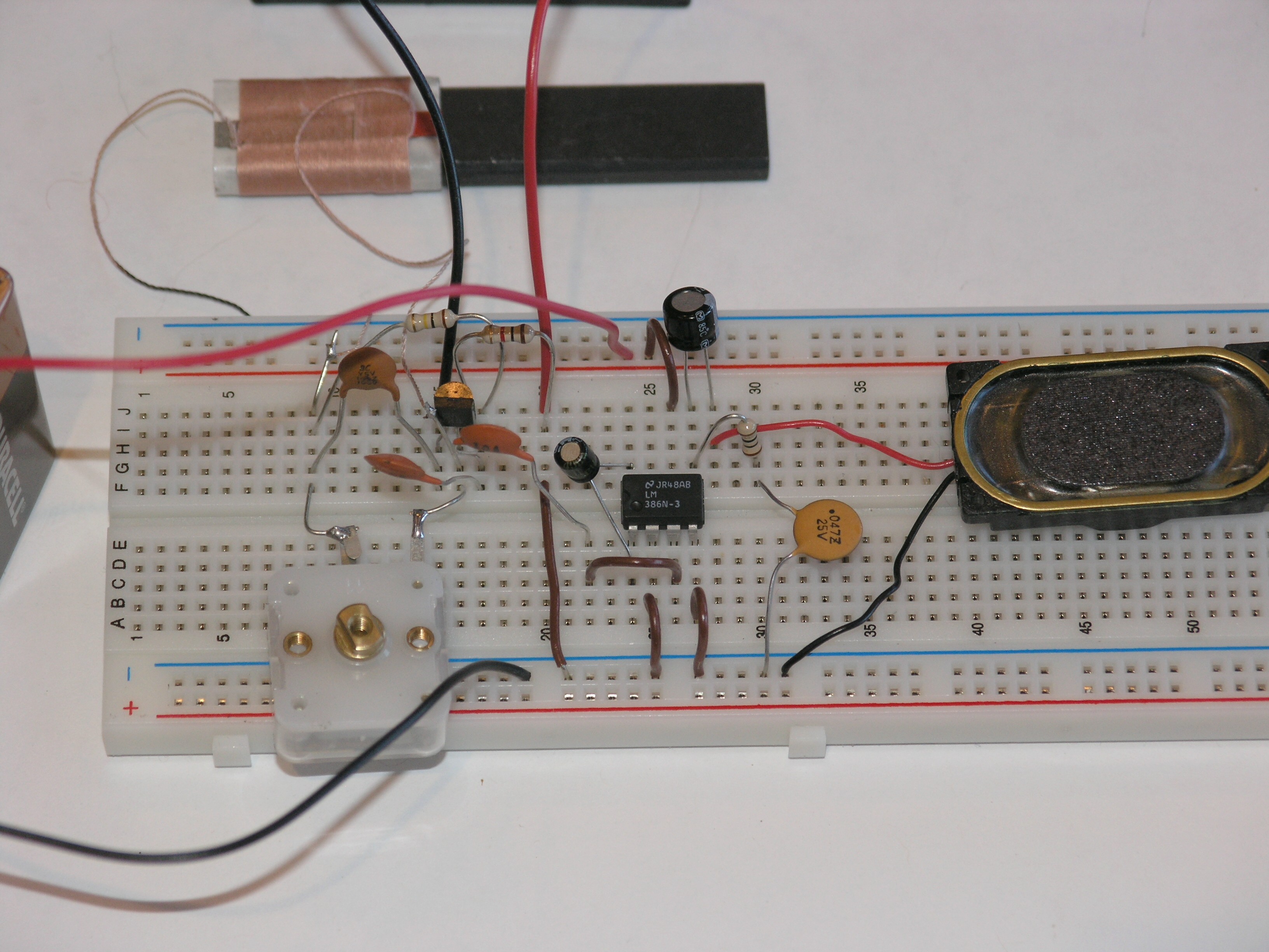
- LM386 amplifier chip at E-24, E-25, E-26, E-27 and F-24, F-25, F-26, and F-27.
- Jumper wire: F-20 to ground rail.
- Jumper wire: C-22 to C-26.
- Jumper wire: A-25 to ground rail.
- Jumper wire: A-27 to ground rail.
- Jumper wire: J-26 to power rail.
- Speaker: red wire to H-27 and black wire to ground rail.
- Negative 9 volt battery wire (black): ground rail.
- Positive 9 volt battery wire (red): power rail.
 Click on photo for a larger picture
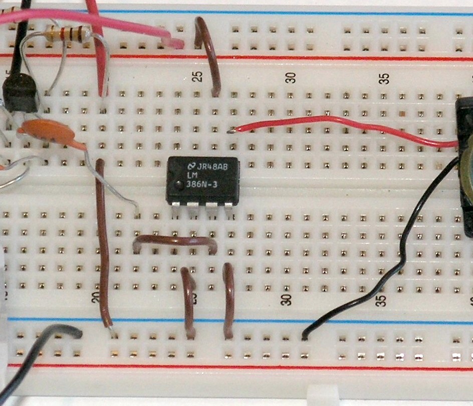
We put a 10 microfarad capacitor connecting pins 1 and 8 of the integrated circuit (put the negative capacitor lead into hole D-24 and the positive capacitor lead into hole G-24). This bypasses a resistor inside the integrated circuit, boosting the gain from 20 to 200. One problem with the circuit so far is that the speaker will get warm and the battery will not last long. This is because a certain amount of DC current is going through the speaker. Direct current (DC) does not make sounds, and so this current is a complete waste of battery power, and simply warms up the speaker coil.
 Click on photo for a larger picture
We fix this problem by putting a 220 microfarad capacitor between the integrated circuit output pin (pin 5, in hole F-27) and the red speaker wire. The positive capacitor lead is put into hole J-27, and the negative capacitor lead is put into hole J-29. The red speaker wire is moved to hole G-29. To prevent the capacitor from changing the sound, we add two more components to create a "filter" that lets only audio frequencies get to the speaker.
 Click on photo for a larger picture
Here we have moved the negative lead of the 220 microfarad capacitor to hole J-28, and moved the red wire of the speaker to H-28. We put a 10 ohm resistor into holes G-27 and G-30. A 0.047 microfarad capacitor goes into hole F-30 and the ground rail. Our amplifier is working pretty well now. But our little speaker has a high tinny voice, because of its size. It would be nice if it had a little more power on the lower frequencies, what we call "bass response". We can arrange to amplify the lower frequencies more than the high ones. We make another filter from a 0.033 microfarad capacitor and a 10,000 ohm resistor, and connect that between the output pin and pin 1 of the integrated circuit. This will feed some of the low frequencies back into the amplifier to be amplified again. We put the 10,000 ohm resistor in holes C-24 and F-29. We put the 0.033 microfarad capacitor in holes I-27 and I-29.
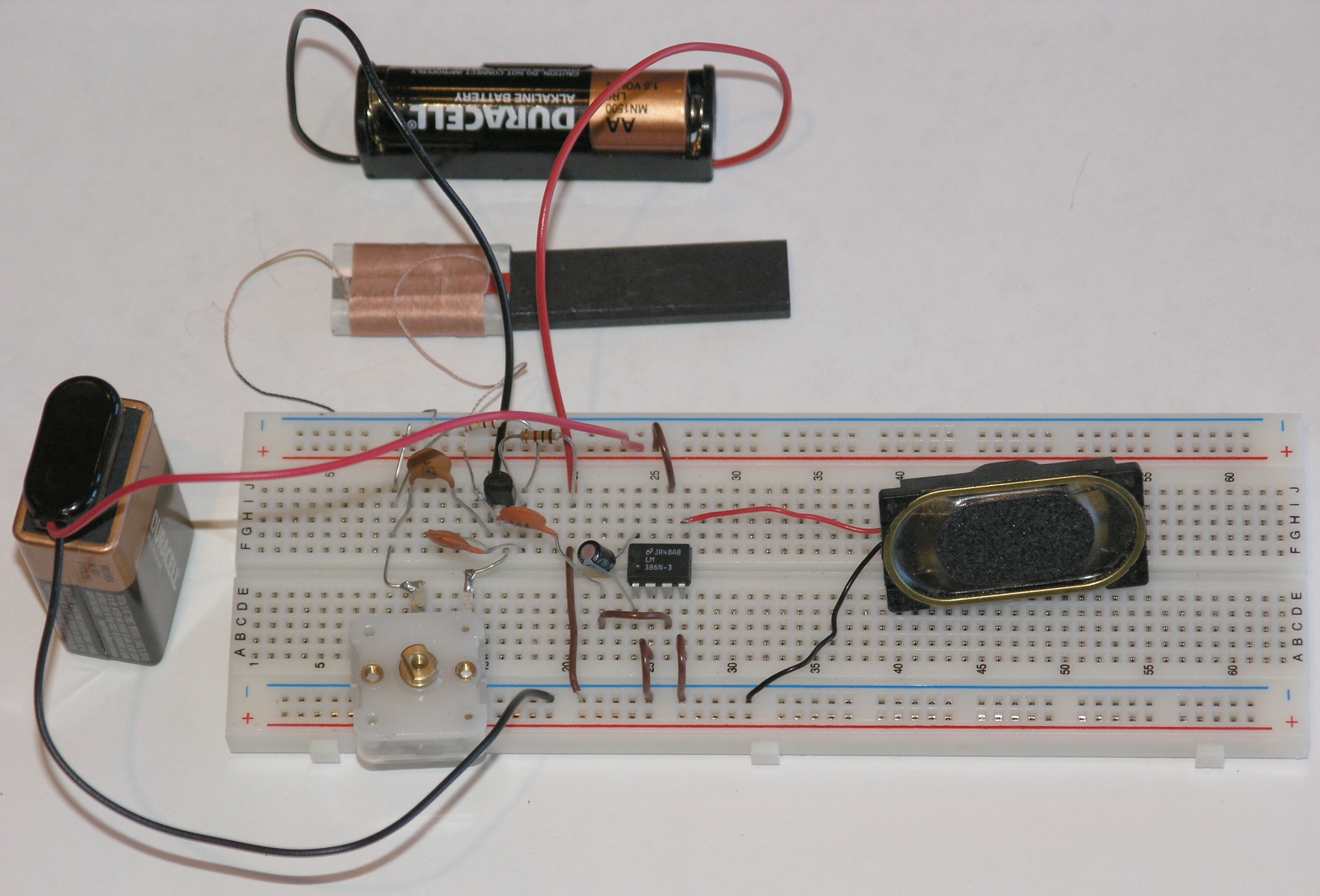
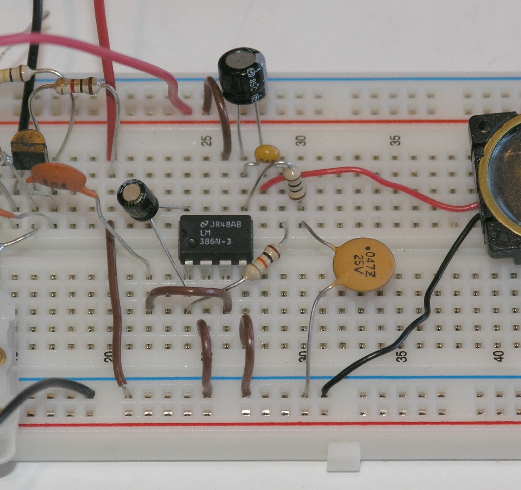 Now our amplifier has a pleasing, more realistic sound.
A more permanent version
As before, we can copy the circuit onto a printed circuit board and solder all of the parts firmly in place.
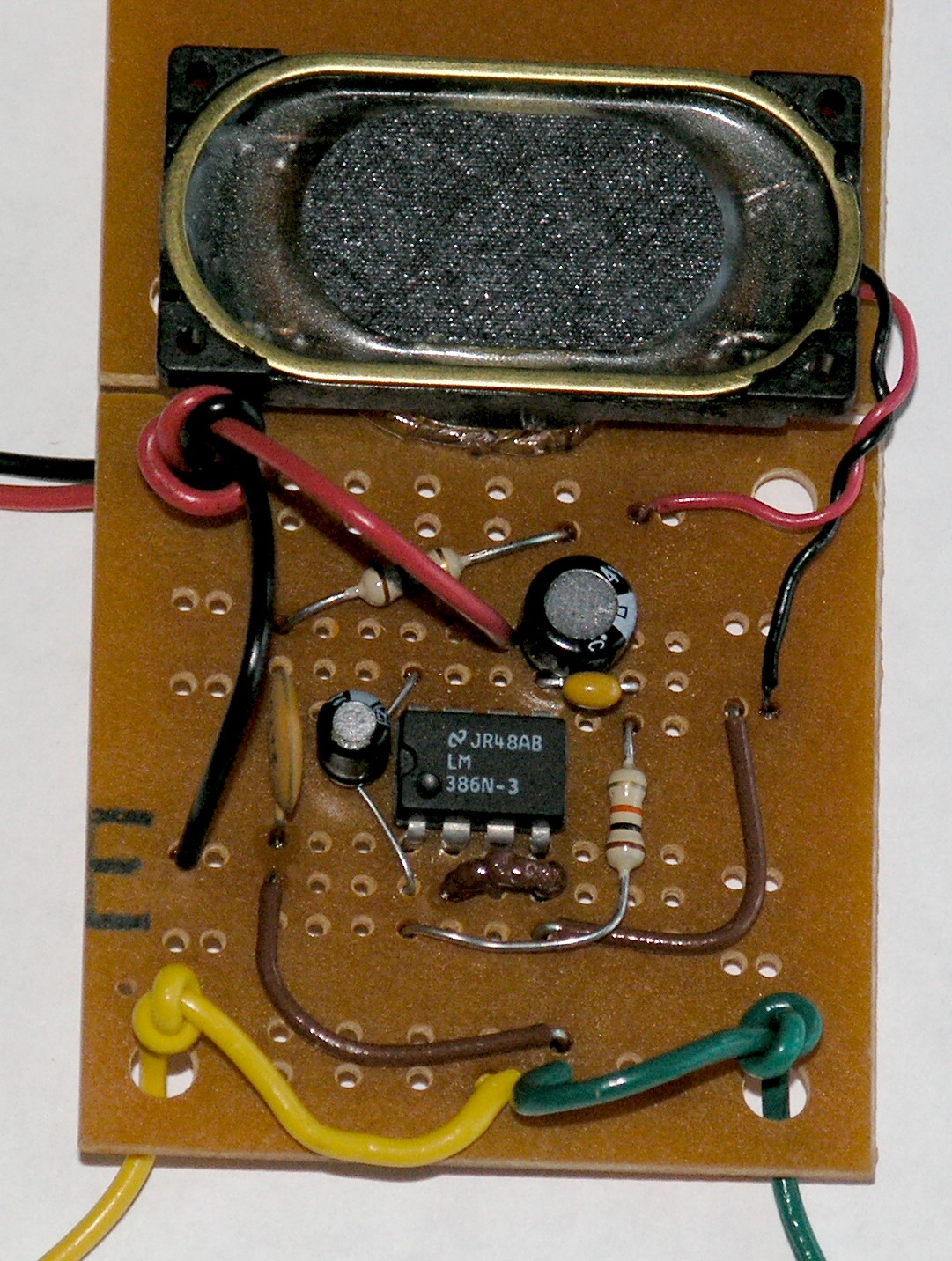 This amplifier can be used for many projects, from amplifying crystal radios
to amplifying the signals from electric fish.
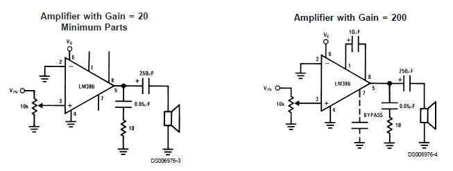
Some schematics for those who aren't using the solderless breadboard:
This amplifier can be used for many projects, from amplifying crystal radios
to amplifying the signals from electric fish.
Some schematics for those who aren't using the solderless breadboard:
 Next A Digital Thermometer.
Del.icio.us
Next A Digital Thermometer.
Del.icio.us
- Science Toys
- Magnetism
- Electromagnetism
- Electrochemistry
- Radio
- Thermodynamics
- Aerodynamics
- Light and optics
- Simple laser communicator
- Make your own 3D pictures
- Making permanent rainbows.
- A solar powered marshmallow roaster
- Make a spectroscope from a CD.
- The impossible kaleidoscope
- Make a solar hotdog cooker
- Exploring invisible light
- A high resolution spectrograph.
- Time-lapse photography.
- High speed photography.
- Stacking photos for high depth of field.
- Biology
- Mathematics
- Computers and Electronics
Some of my other web sites:

Send mail to Simon Quellen Field via [email protected]