- Science Toys
- Magnetism
- Electromagnetism
- Electrochemistry
- Radio
- Thermodynamics
- Aerodynamics
- Light and optics
- Simple laser communicator
- Make your own 3D pictures
- Making permanent rainbows.
- A solar powered marshmallow roaster
- Make a spectroscope from a CD.
- The impossible kaleidoscope
- Make a solar hotdog cooker
- Exploring invisible light
- A high resolution spectrograph.
- Time-lapse photography.
- High speed photography.
- Stacking photos for high depth of field.
- Biology
- Mathematics
- Computers and Electronics
Building a computer controlled laser data transmitter
Although computers got their name from their ability to calculate, one of the main uses for computers today is in communications. Our modern telephone system is a large collection of computers, communicating with one another by sending pulses of laser light through optical fibers.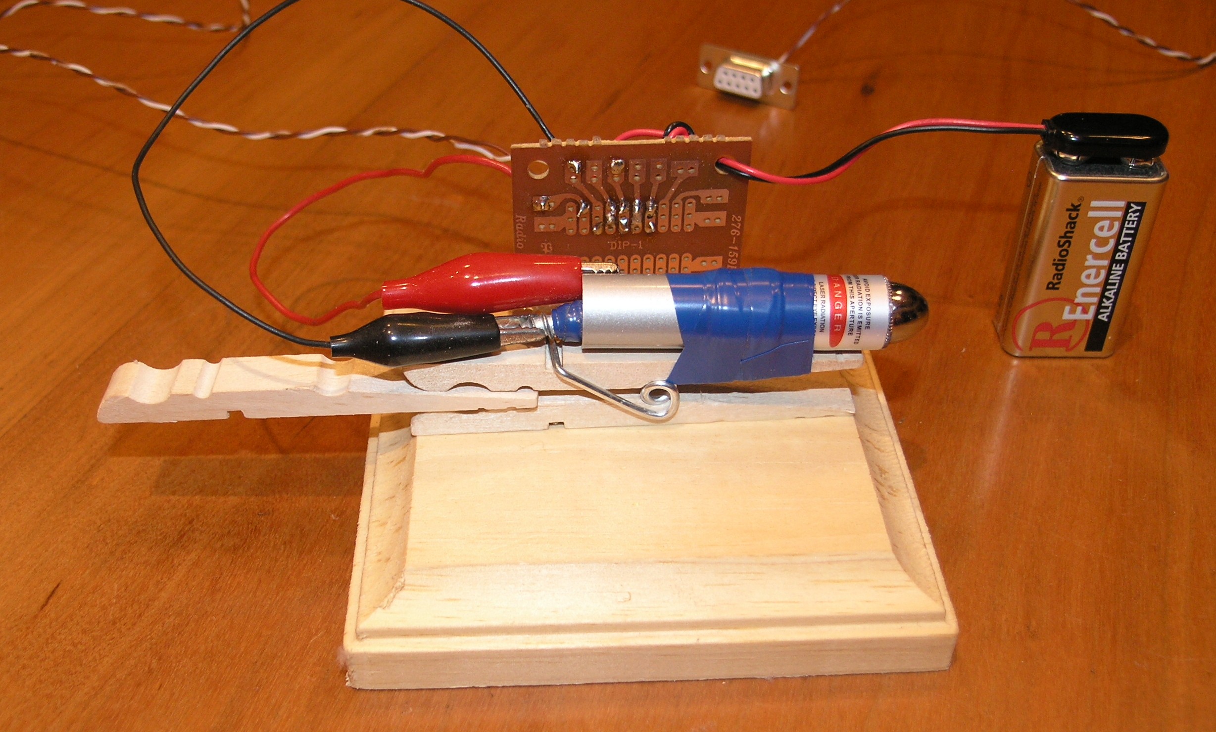
Click on photo for a larger picture
We can do the same thing at home. In this project, we will build a laser transmitter that the computer will control, sending data by flashing the laser on and off. But we will eliminate the optical fibers, and just send the light through the air, in what is called free space laser data transmission. The computer controlled laser data transmitter needs these parts:
- A pocket laser pointer
We carry this item in our catalog. - A serial port connector
We use a 9 pin RS232 connector. You can take apart an old serial cable, or buy a new connector from an electronics or computer store. We carry this item in our catalog. - An NPN transistor
Almost any type will do, such as the 2N4401 or 2N2222A. We carry this item in our catalog. - A 470 ohm resistor
This resistor will have color codes Yellow Purple Brown and Gold. We carry this item in our catalog. - A light emitting diode
We use a clear lensed red LED, but most any LED will do. We carry this item in our catalog. - A generic printed circuit board
This is not really required, but makes assembly easier. We use the Radio Shack 276-159B. We carry this item in our catalog. - An alligator test lead
This is a piece of wire with alligator clips at each end. We used half of a red one and half of a black one, to make it easy to describe how to connect them, but a single test lead cut in half will do nicely. It does not harm the laser to connect them wrong -- just switch them around if the laser doesn't light up. We carry this item in our catalog. - A nine volt battery clip
This is a clip on connector for a 9 volt battery. We carry this item in our catalog. - A spring-type clothes pin
- A screw or nail about 2 inches long with a flat head
- A small block of wood for a base
- A nine volt battery
- A bit of tape and glue to hold it all together
Modifications to the laser
We will not actually modify the laser, so it will be easy to undo the project and still have a working laser pointer. But we will be removing the batteries, taping down the ON switch, and inserting a small screw where the batteries were, to make it easy to connect the laser to the transmitter circuit we will build.
Click on photo for a larger picture
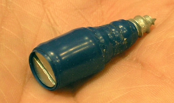
With the batteries removed, we can look into the back end of the laser and see the small spring that normally connects to the negative terminal of the battery. We can also see the switch that turns the laser on — it is the little black box with the red button.
Click on photo for a larger picture
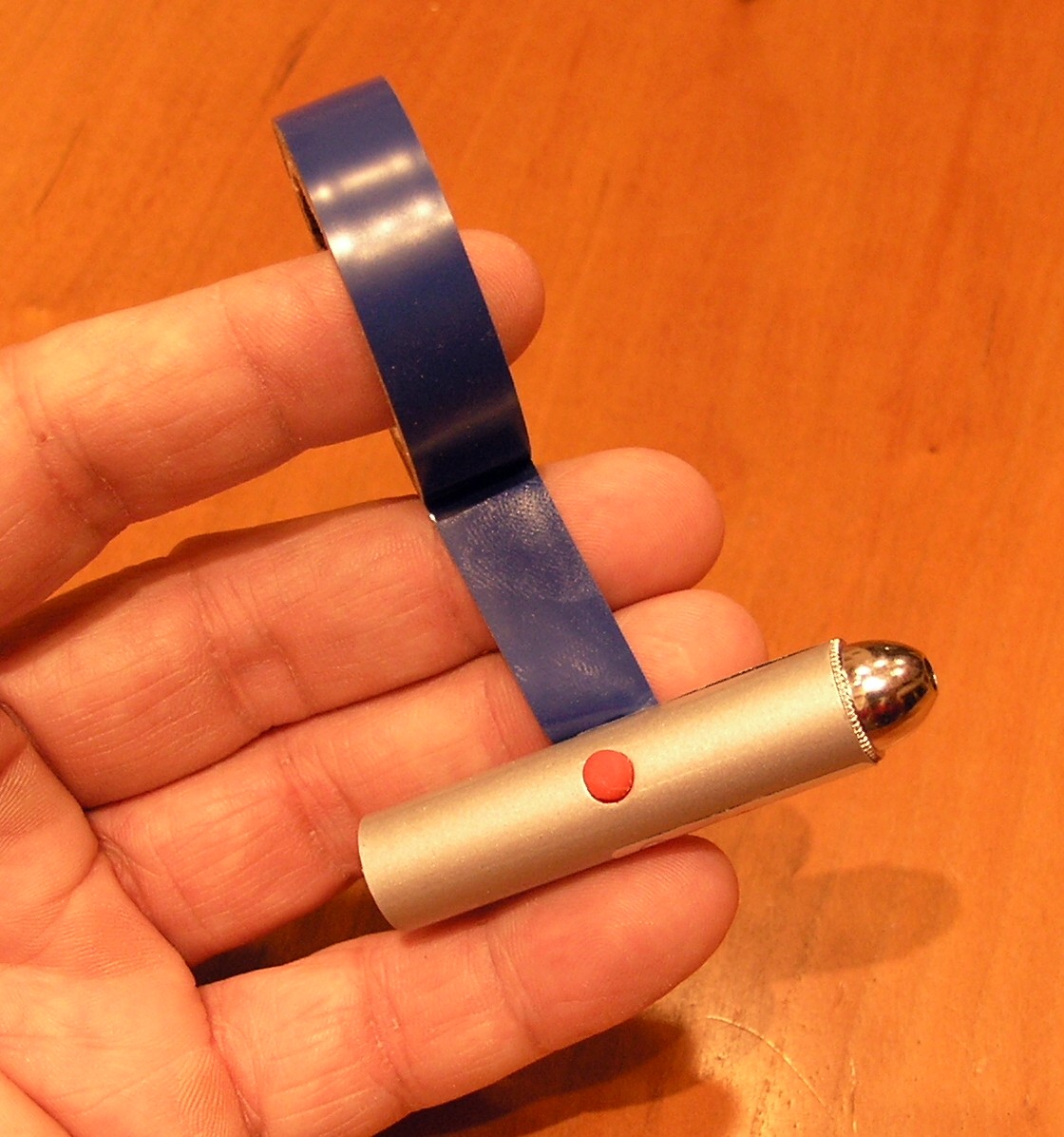
To make it easier to connect the little spring to our circuit, we will wrap some tape around a small screw, and place the screw head against the spring. The tape will be wound around the screw until it makes a snug fit inside the laser, compressing the screw a little bit.
Click on photo for a larger picture
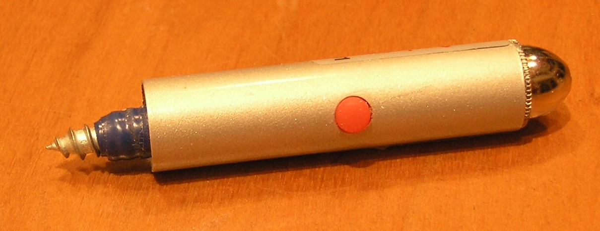
Next, we use some tape to hold the ON button down. We will be turning the laser on and off with our circuit, so the button will no longer be used, and must remain in the ON position at all times.
Click on photo for a larger picture
The computer will communicate with our circuit through its serial port. If your computer does not have a serial port, there are inexpensive USB serial ports you can buy that will connect easily to your computer and will work fine for our project.
Click on photo for a larger picture
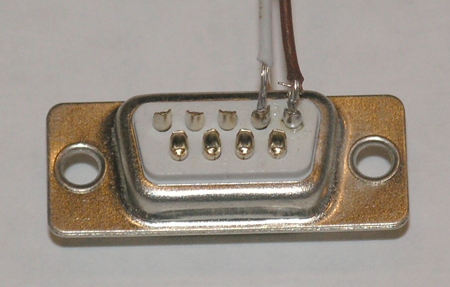
We will use a 9 pin female serial connector, attaching wires to pins 4 and 5 only. Those pins are the Data Terminal Ready pin (pin 4) and the Ground pin (pin 5).
Click on photo for a larger picture
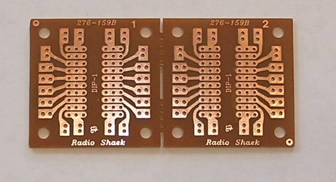
We will use a generic printed circuit board for this project, although all of the parts could simply be soldered together without it, or even connected with alligator test leads. But soldering the parts to a printed circuit board makes the project sturdy, and guarantees the parts will stay connected.
Click on photo for a larger picture
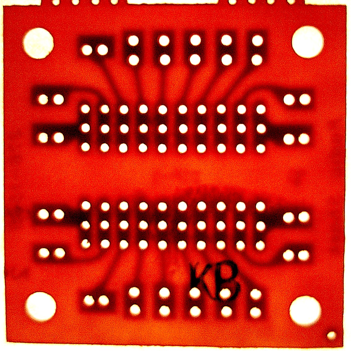
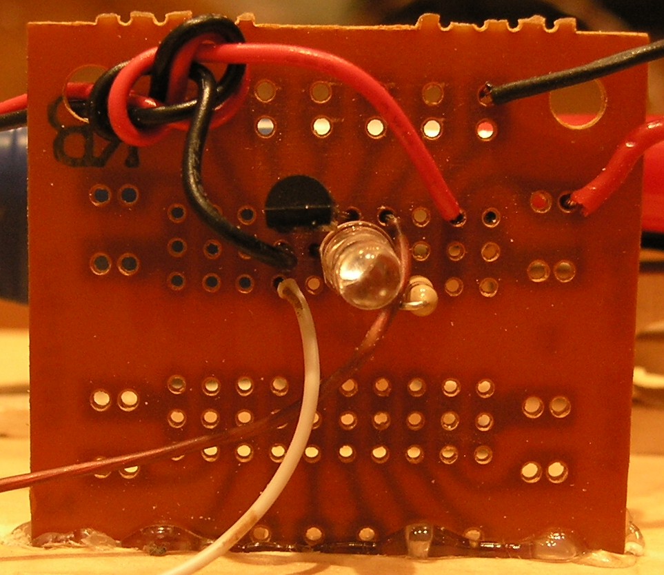
One side of the board has copper foil printed on it. The other side of the board will have our components. The two sides of the board are called the solder side (where we do the soldering) and the component side (where the transistor, LED, and resistor will be). When we hold the board up to the light, we can see the shadow of the copper foil showing through on the component side.

Click on photo for a larger picture
I have drawn the outlines of the components onto the following picture of the circuit board. Some of the components seem to overlap in my drawing — this is because the parts will either be bent out of the way a little bit, or the leads will be left long, so one part will be higher than the others. You can choose to use either method of fitting the parts onto the board. Solder the transistor onto the board first. With the flat side of the transistor facing the bottom of the page, the emitter, base, and collector wires will fit into three holes, and the wires soldered to the copper on the other side of the board. Next, solder the LED onto the board by placing its leads through the proper holes and soldering them to the foil on the back side of the board. The LED has a flat side, which should face the left. The left lead is the cathode, and the right lead is the anode. The cathode will connect to the base lead (the middle lead) of the transistor, one hole down. The cathode lead is shorter than the anode lead. Next solder the resistor in place. It will stand up straight, and the top lead will be bent over to go into the hole below the transistor's collector lead. Cut off the excess leads on the solder side of the board, so it is neat and the leads don't accidentally bend onto one another. Next solder the battery clip wires onto the board, as shown in the photo. I like to feed them through a large hole and tie a knot in them before I solder them to the board, to prevent the heavy battery from pulling the wires off the board if it falls. The negative (black) wire connects to the emitter lead of the transistor, one hole down. The red positive wire goes into the next unused hole to the right, just past the resistor. Now we solder the wires from the 9 pin serial connector to the board. The wire from pin 4 goes in the hole below the black battery wire, so it connects to the emitter of the transistor and the negative terminal of the battery. The wire from pin 5 goes into the hole just above the anode lead from the LED, so it is connected to the LED anode. Lastly, we cut the alligator test lead in half, and solder one half to the hole that leads to the red battery wire, and the other half to the hole that leads to the bottom lead of the resistor.
Click on photo for a larger picture
In schematic form, the circuit looks pretty simple, since there are only four parts:
We are now ready to connect all the parts together. We tape the laser to the clothes pin as shown in the photo, and glue the clothes pin to the block of wood. We insert the wedge shaped end of half of another clothes pin between the jaws of the first clothes pin. This arrangement makes it easy to make very small adjustments to the vertical angle of the laser beam, making aiming the laser much easier. Connect the positive alligator test lead to the barrel of the laser, and the negative test lead to the pointed end of the screw. Connect the battery to the battery clip.

Click on photo for a larger picture
Lastly, plug the serial connector into the serial port of the computer. The LED and the laser should both light up as soon as you do this. If they don't, then carefully check all of your connections, and make sure that you didn't accidentally bridge two of the copper foil traces together with solder. If the LED lights up but the laser does not, check the connections, and also check that the button on the laser is firmly depressed.
Controlling the transmitter
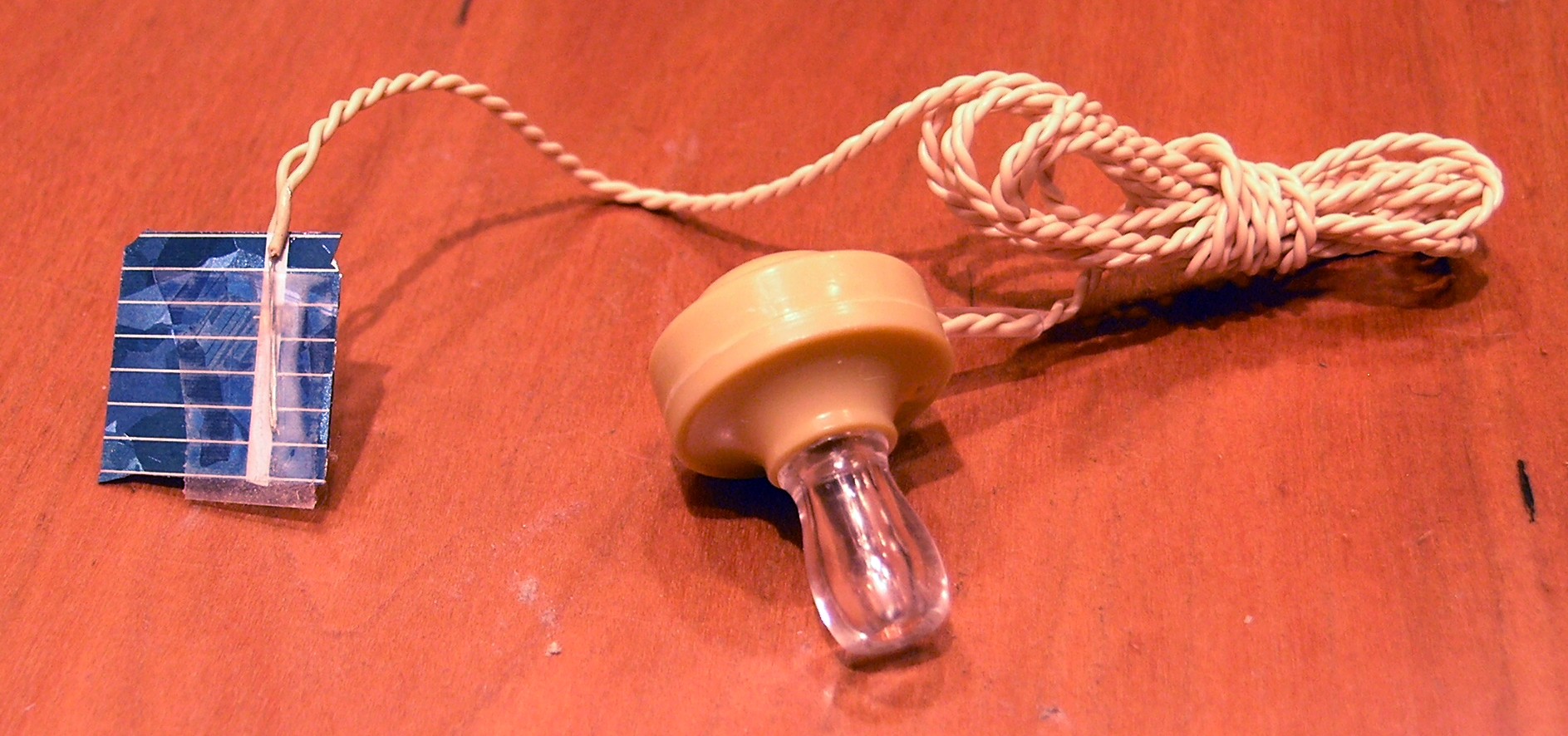
To send a message, we now use the same computer program that we used in the Computer Controlled Radio Transmitter project to convert what we type into Morse code, and turn the laser on and off in dots and dashes. There is one small difference in the setup, however. The laser is not directly powered by the serial port, as the radio transmitter was. The laser circuit has a transistor switch in it. The transistor inverts the signal. This means that when the serial port is turned on, the transistor turns the laser off. When the serial port turns off, the transistor turns the laser on. This is caused by the simple circuit we use. We could have used two transistors to prevent the inversion, but instead, we simply tell the computer program to invert the signals before it sends them. This is easier and cheaper than adding another transistor.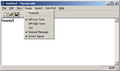 To receive the morse code signals, we can use a very simple receiver,
made from a piezoelectric earphone and a small solar cell.
(We carry this item in our
catalog.)
To receive the morse code signals, we can use a very simple receiver,
made from a piezoelectric earphone and a small solar cell.
(We carry this item in our
catalog.)
Click on photo for a larger picture
You can also connect a phono plug to the solar cell instead of the earphone, and plug it into the sound card of another computer and use the same morse code receiving program as in the Computer Controlled Radio Transmitter project.
How does it do that?
Each of the four components in the circuit perform their own special task.
The signal coming in from the serial port swings between 25 volts DC to -25 volts DC. The LED not only lights up to show that the signal got there, but because it is a diode, it cuts off the negative swings of the signal, so the transistor only sees a signal of 0 volts or 25 volts. (Most serial ports never actually go much higher than 12 volts, but the RS-232 specifications allow as much as 25 volts.) The transistor is set up to act as a simple switch. It has three leads — the base, the emitter, and the collector. The emitter is connected to the negative side of the power supply, which is called ground, because it is often connected to the earth in electronics and radio circuits. The base is connected to the LED that lights up when the serial port signal is on. When the base of the transistor sees the voltage go from 0 to anything more than about a volt, the transistor goes from the "off" state to the "on" state, allowing electrons to flow from the emitter to the collector. The collector is connected to the 470 ohm resistor. This resistor is needed to prevent too much current from flowing into the laser, which would damage it. We use a 470 ohm resistor because we want the current going through the laser to stay below 30 milliamperes. There is a simple rule for calculating how much resistance you need to limit the current. It is called Ohm's Law. It says that the current is equal to the voltage divided by the resistance: amperes = volts ÷ ohms We have 9 volts and 470 ohms, so 9 ÷ 470 is about 0.019 amperes, or 19 milliamperes (a milliampere is 1/1,000th of an ampere). This is enough to light the laser brightly, and yet well below the 30 milliampere limit that would damage the laser. Finally, when the electrons flow from the emitter to the collector and then through the resistor, they get to the laser, and cause it to light up, sending a beam of light we can detect as far as a mile away at night, or across the street in the daytime. Next: Fun with Solderless Breadboards Del.icio.us
- Science Toys
- Magnetism
- Electromagnetism
- Electrochemistry
- Radio
- Thermodynamics
- Aerodynamics
- Light and optics
- Simple laser communicator
- Make your own 3D pictures
- Making permanent rainbows.
- A solar powered marshmallow roaster
- Make a spectroscope from a CD.
- The impossible kaleidoscope
- Make a solar hotdog cooker
- Exploring invisible light
- A high resolution spectrograph.
- Time-lapse photography.
- High speed photography.
- Stacking photos for high depth of field.
- Biology
- Mathematics
- Computers and Electronics
Some of my other web sites:

Send mail to Simon Quellen Field via [email protected]