- Science Toys
- Magnetism
- Electromagnetism
- Electrochemistry
- Radio
- Thermodynamics
- Aerodynamics
- Light and optics
- Simple laser communicator
- Make your own 3D pictures
- Making permanent rainbows.
- A solar powered marshmallow roaster
- Make a spectroscope from a CD.
- The impossible kaleidoscope
- Make a solar hotdog cooker
- Exploring invisible light
- A high resolution spectrograph.
- Time-lapse photography.
- High speed photography.
- Stacking photos for high depth of field.
- Biology
- Mathematics
- Computers and Electronics
A digital thermometer
With the easy availability of inexpensive digital multimeters, and integrated circuit temperature sensors, it is now very easy to build a sensitive and accurate digital thermometer that can be used for many experiments around the house or in the amateur laboratory. There are two tenperature sensors that make this particulary easy -- the LM34 and the LM35. These are callibrated in Fahrenheit and Celsius respectively, and when read by the meter, they produce ten millivolts per degree in their respective scales, so the meter can be directly read in temperatures, down to a tenth of a degree. The digital thermometer needs these parts:- A multimeter. We chose a digital multimeter for accuracy and easy reading.
- An LM34 integrated circuit temperature sensor for Fahrenheit.
- An LM35 integrated circuit temperature sensor for Celsius.
- A 180,000 ohm resistor
This resistor will have four colored bands on it. The colors will be brown, gray, yellow, and gold. - A nine volt battery
- A nine volt battery clip
- Two alligator test leads
- Three long wires (optional)
- Electrical tape or heat shrinkable tubing (optional)
Click on photo for a larger picture
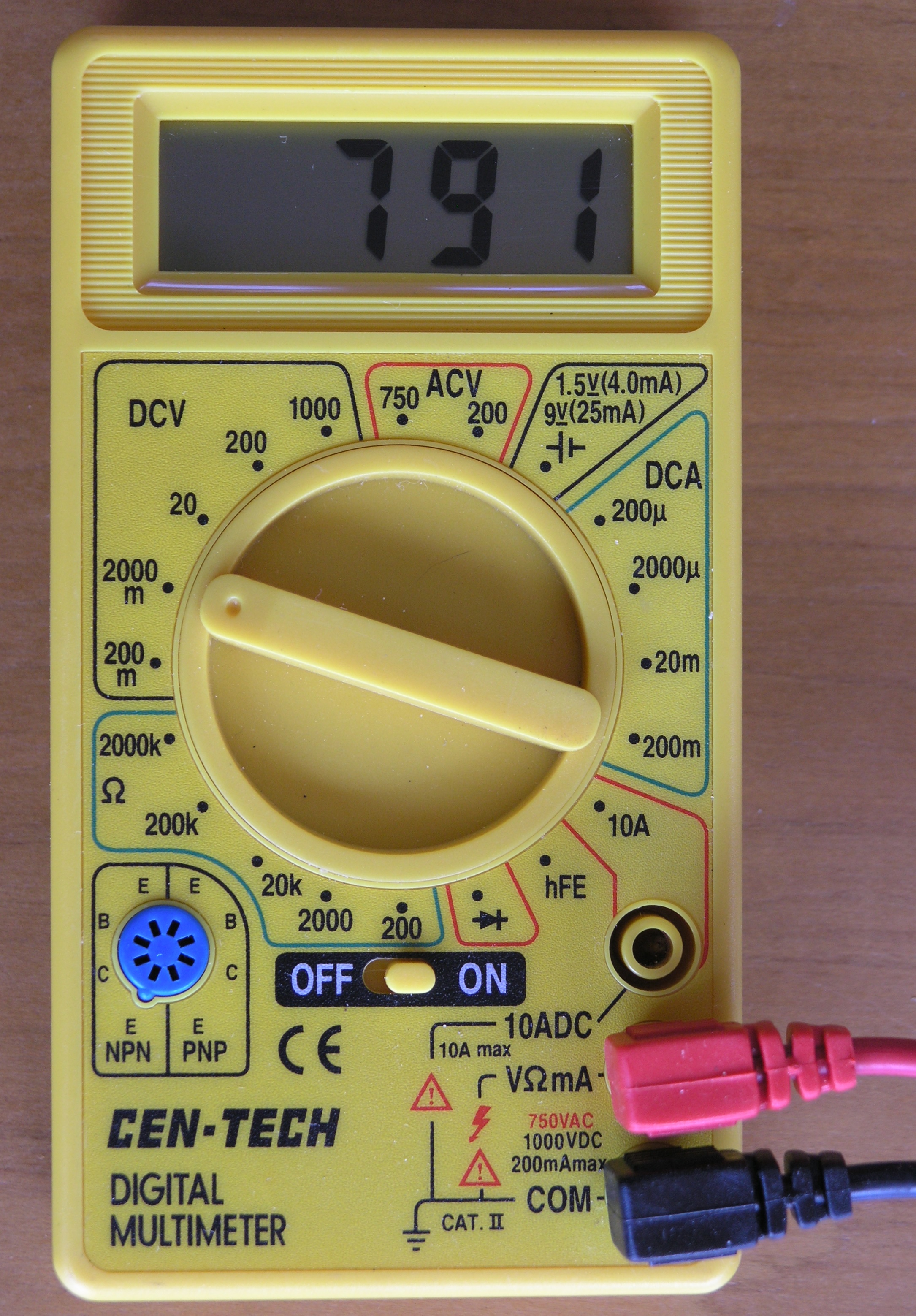
Shown above is a multimeter, set to read 0 to 2,000 millivolts (zero to two volts). Note that the dial switch is set to "2000 m". It is currently reading 791 millivolts, which corresponds to 79.1 degrees Fahrenheit (since it is connected to the LM34 sensor).
Click on photo for a larger picture
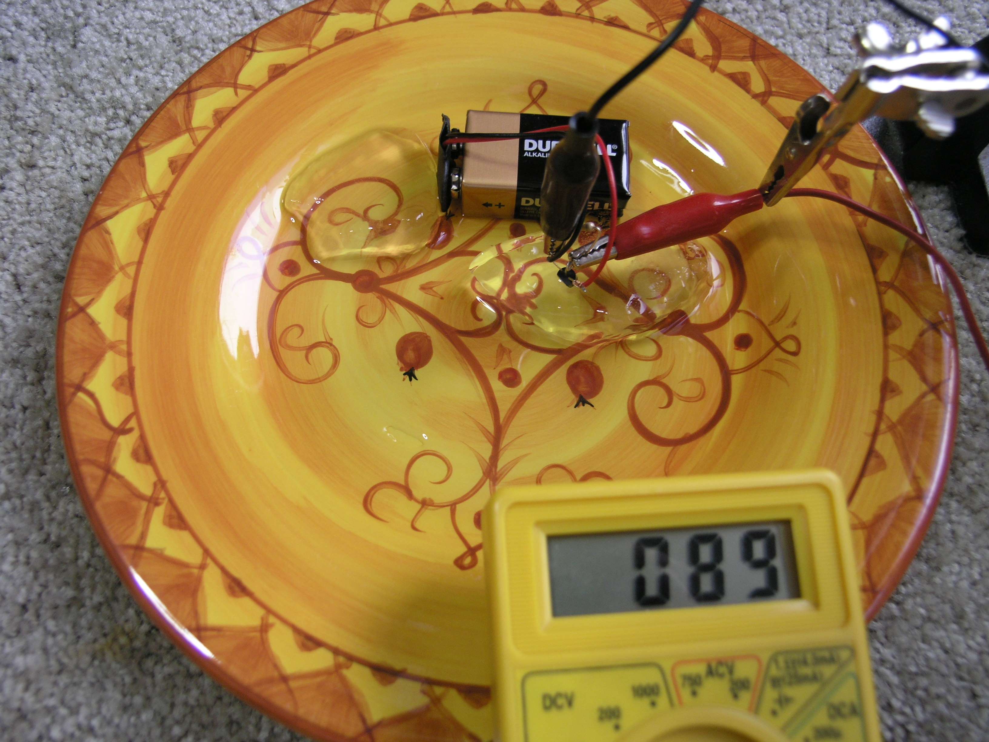
Above, we have placed an LM35 sensor on top of an ice cube, and the pool of water melted from the ice is reading 8.9 degrees Celsius. For this experiment we have simply connected alligator clips to two of the leads of the sensor, and wrapped the third lead with the red wire from the battery clip. No soldering, nothing fancy, and we have a digital thermometer in the time it takes to unwrap the meter and clip on the test leads.
Click on photo for a larger picture
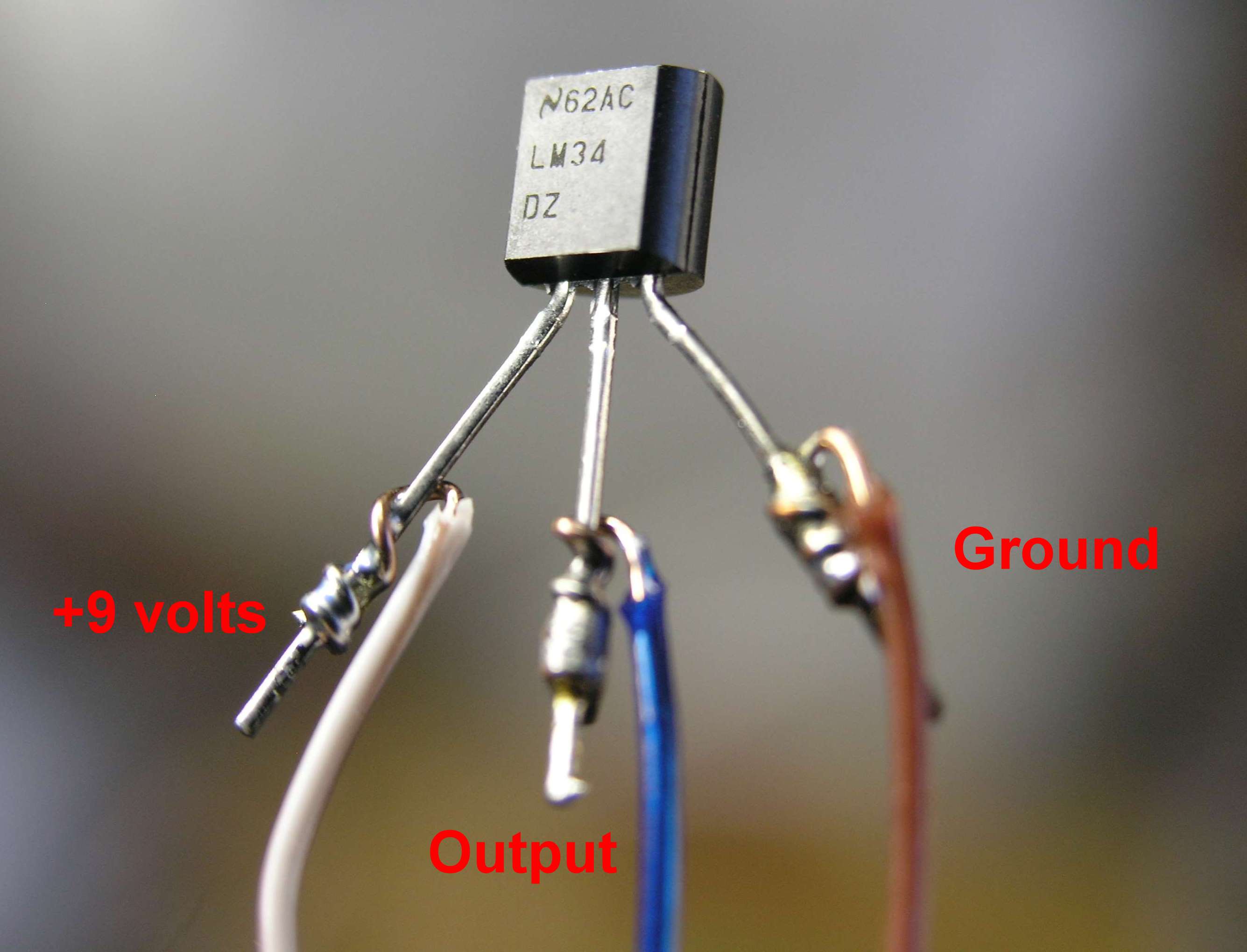
For a more permanent thermometer, we solder three long wires (about 5 feet is nice) to the three leads of an LM34 Fahrenheit sensor. Use three different colors, and note which ones are attached to which leads. We put a little electrical tape around the middle lead so it won't touch the other two, and then wrap the whole thing in electrical tape, or in this case, put it into a short length of heat shrinkable tubing, and warm it up so the tubing shrinks tightly around the whole assembly. We made the wires long so that we can measure things inside boxes or behind doors. Five feet makes it easy to place the sensor end in the refrigerator or freezer, and have the meter stay outside where it is easy to measure. This arrangement is great for incubators for eggs, and terrariums, or (with proper waterproofing) aquariums.

Click on photo for a larger picture
At the other end of the long wires, we connect the battery clip and the resistor. Note that the wire colors help ensure that the right connections are made. In our case, the red wire from the battery clip is soldered to the brown and white striped wire, and the black wire from the battery clip is soldered to the brown wire. The brown wire is wrapped around one end of the resistor, and the blue wire is wrapped around the other end of the resistor. We can solder them later if we wish.
Click on photo for a larger picture
In the photo above you can see how the heat shrinkable tubing makes a nice neat temperature probe, with only the top of the sensor peeking out of the shrunken tube. The alligator test leads are attached to the resistor, and the other ends are clipped onto the meter probes, as shown in the photo below.
Click on photo for a larger picture
How does it do that?
The internal workings and theory of the LM34 integrated circuit temperature sensor is explained in minute detail by the manufacturer.
Click on drawing for a larger picture
The circuit diagram is shown above. Briefly, there are two transistors in the center of the drawing. One has ten times the emitter area of the other. This means it has one tenth of the current density, since the same current is going through both transistors. This causes a voltage across the resistor R1 that is proportional to the absolute temperature, and is almost linear across the range we care about. The "almost" part is taken care of by a special circuit that straightens out the slightly curved graph of voltage versus temperature. The amplifier at the top ensures that the voltage at the base of the left transistor (Q1) is proportional to absolute temperature (PTAT) by comparing the output of the two transistors. The amplifer at the right converts absolute temperature (measured in Kelvin) into either Fahrenheit or Celsius, depending on the part (LM34 or LM35). The little circle with the "i" in it is a constant current source circuit. The two resistors are calibrated in the factory to produce a highly accurate temperature sensor. The integrated circuit has many transistors in it -- two in the middle, some in each amplifier, some in the constant current source, and some in the curvature compensation circuit. All of that is fit into the tiny package with three leads. Del.icio.us
- Science Toys
- Magnetism
- Electromagnetism
- Electrochemistry
- Radio
- Thermodynamics
- Aerodynamics
- Light and optics
- Simple laser communicator
- Make your own 3D pictures
- Making permanent rainbows.
- A solar powered marshmallow roaster
- Make a spectroscope from a CD.
- The impossible kaleidoscope
- Make a solar hotdog cooker
- Exploring invisible light
- A high resolution spectrograph.
- Time-lapse photography.
- High speed photography.
- Stacking photos for high depth of field.
- Biology
- Mathematics
- Computers and Electronics
Some of my other web sites:

Send mail to Simon Quellen Field via [email protected]