We had fun measuring temperatures. Now it is time to actually change the temperature.
A water bath is often used to keep something at a constant temperature. The thermal mass of the water keeps the temperature from changing rapidly. We use our digital temperature sensor to measure how warm the water is, and a simple electric heater to warm it up if needed.
The water bath can then be used to incubate bacterial cultures (care to make some yogurt?). Or we can adapt the system to keep a tropical fish tank at the right temperature, despite changes in air temperature or sunlight from a window. The system is also adaptable to make a chicken egg incubator, or even a sous vide cooker.
To make our temperature controlled water bath, we will start with a well-insulated container. This will allow us to use a smaller heater, thus saving energy. The smaller heater is also simpler to control with the tiny computer, since all we need is a power transistor to handle the current (about 3.5 amperes for our 18 watt heater).
We chose a Styrofoam shipping box sold to ship items chilled with dry ice.

These boxes are sturdier than the typical picnic cooler, but a small picnic cooler will work fine.
We also need two copper wires. We chose 18 gauge wire (the uninsulated ground wire from some household wiring). It is thick enough to carry the current we will be using, and yet thin and flexible enough to easily crimp the heater wire onto.

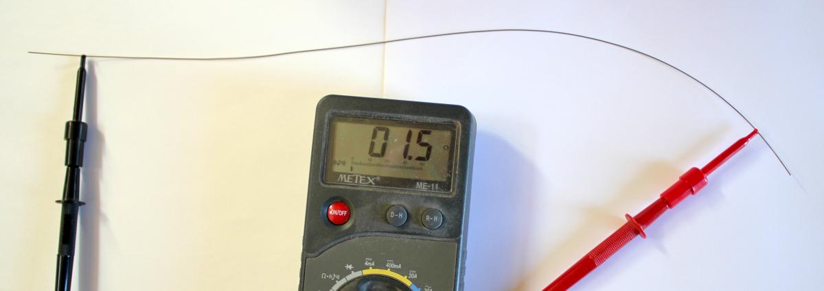
The heater wire comes next. We use 22 gauge bare nichrome 60 wire. It has 1.06 ohms per foot. We use an ohmmeter to measure out a length that will give us 1.5 ohms.
To make the wire fit nicely in the box, we coil it up around a pencil. We then remove the pencil.

Now we wrap the free ends of the coil around the copper wires, and bend the copper down over the nichrome, crimping it with pliers to form a good connection. The remaining free ends of the copper wire we then push through the lid of the box.

An ice-pick made a nice hole in the lid to thread the cable from the DS18B20 temperature sensor through the lid of the box. This is a waterproof sensor with the DS18B20 inside. You can make your own by just coating the DS18B20 with silicone rubber glue after soldering the cable to it. This one was purchased ready-made.

For this project we chose to solder the temperature sensor wires and other connections directly to the tiny computer, to show that you don't need to use a solderless breadboard all the time. The power leads of the DS18B20 go to +5 and ground, and the sense lead is soldered to pin D2, the same pin we used in earlier projects. A 4.7k ohm resistor is connected from +5 to D2, to pull the value at that pin up to HIGH when the DS18B20 isn't pulling it to LOW.
The transistor is a TIP31 power transistor. The base is connected to pin D3. The emitter is connected to ground, and the negative side of a 5 volt wall-wart-style power supply. The positive side of the power supply is connected to one leg of the heater. The other leg of the heater is connected to the collector (the center pin) of the TIP31.

In diagram form, the circuit looks like this:

In use, the tiny computer will set D3 to HIGH when it wants to heat the water. That turns on the TIP31 power transistor, which is acting like a switch for the heater, allowing current from the power supply to flow through the nichrome wire. If the wire is not in the water, it will glow red hot, so you will always want to make sure there is enough water in the box to cover the heater.
A program to measure the temperature and turn on the heater if it is too low would be simple to write, and would keep the temperature close to where we want it to be. But we can take advantage of the processing power of the tiny computer to do a better job, and make the heater work optimally, coming up to the desired temperature quickly, and settling down at the precise temperature without overshooting too much.
The trick is to design a proportional, integral, derivative controller (called a PID controller for short).
That sounds complicated, but it actually only involves three concepts.
The first is proportional. That simply means that the amount of heat we add is proportional to the difference between the temperature of the water and the temperature we want the water to be. If we are several degrees off of our target, we turn the heater on full blast. If we are very close to our target temperature, we only add a little heat.
That is better than just turning on the heat full blast whenever the temperature is even a tiny bit below the target. But it turns out that either way isn't perfect. We get close to the target, but never settle on it.
To fix this, we need something that remembers the heat we added in the past, and adjusts the new heat setting based on the average work we have been doing recently. This is the second concept, integral. We keep track of the average difference between our target temperature and the water temperature each time we take a measurement (this is calledintegrating). Now the temperature settles out exactly onto the target, after wavering up and down a little bit.
We can limit the wavering up and down by using the third concept, derivative. If we could predict where the temperature was going to be on the next measurement, we could adjust the amount of heat we add to reduce any overshoot. Predicting the future is what a derivative does. The derivative is simply the rate of change. If the current temperature was only slightly different from the last time we measured it, the rate of change is small. If the temperature was very different from the current temperature, the rate of change was high. A high rate of change tells us that we can predict the next measurement will also be high. If we are close to the target, we don't want a high rate of change, so the derivative can slow down the heating by putting less power into the heater.
The code for the PID controller is here.
The heart of the program is the PID class:
enum
{
SAMPLE_TIME_IN_MS = 300,
MILLISECONDS_PER_SECOND = 1000,
OUTMIN = 0,
OUTMAX = 255
};
class PID
{
double kp; // Proportional coefficient
double ki; // Integral coefficient
double kd; // Derivative coefficient
double previous_input;
unsigned long lastTime;
int output;
public:
double Integral;
double Target;
PID( double Kp, double Ki, double Kd, double target )
{
Integral = 0;
previous_input = target;
output = 0;
Target = target;
double seconds_per_sample = double( SAMPLE_TIME_IN_MS )
/ MILLISECONDS_PER_SECOND;
kp = Kp;
ki = Ki * seconds_per_sample;
kd = Kd / seconds_per_sample;
lastTime = millis() - SAMPLE_TIME_IN_MS;
}
int
out( double input )
{
unsigned long now = millis();
unsigned long timeChange = now - lastTime;
if( timeChange >= SAMPLE_TIME_IN_MS )
{
double error = Target - input;
Integral += ki * error;
double Proportional = kp * error;
double Derivative = kd * (previous_input - input);
previous_input = input;
if( Integral > OUTMAX )
Integral = OUTMAX;
else if( Integral < OUTMIN )
Integral = OUTMIN;
output = int( Proportional + Integral + Derivative );
if( output > OUTMAX )
output = OUTMAX;
else if( output < OUTMIN )
output = OUTMIN;
lastTime = now;
}
return output;
}
};
The out() method does all the work.
It subtracts the current temperature from the target temperature to get the error.
The Integral is the sum of all errors multiplied by the constant ki. This is a tuning constant passed into the constructor, and it says how much to weight the Integral part of the PID controller.
The Proportional part is simply the error multiplied by the weight constant for the proportional part (kp).
The Derivative is the constant kd times the difference between this input and the previous one.
The output is just the sum of the three factors. We make sure it is never greater than our maximum value.
Lastly, we return the result.
In use, we first initialize our PID controller, passing in the weights for the P, I, and D factors, and the target temperature:
PID pid( 340, .6, 20, 98.6 );
In the loop() function, we get the current temperature, and pass it to the out() method. We get the result, and use that to control the heater using analogWrite():
double f = t.fahrenheit( 0 );
int out = pid.out( f );
analogWrite( PIN3, out );
The rest of the code is just there to print out the data values so we can store them and graph them later.