Finally, we are going to do some actual science.
Well, in a moment at least. First we are going to make life easier by soldering some pins onto our little computer, so that we won't have to ever solder again. The pins will let us plug our computer into a solderless breadboard, a nifty little gadget that will let us just plug wires into holes instead of soldering things to make connections.
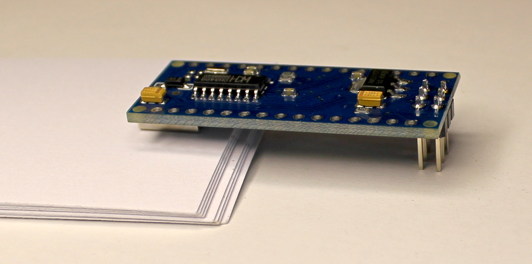
The little computer comes with three sets of pins that we will be soldering in place. First, we will attach the small set of six pins to the top of the board. This is most easily done by turning the board upside down, and inserting the pins into the six holes opposite the USB connector. To keep them straight, we rest the other end on a stack of paper just the right height to keep things level. Solder each pin, being careful not to have any blobs of excess solder connecting the pins. Just a little bit of solder is all each pin needs.
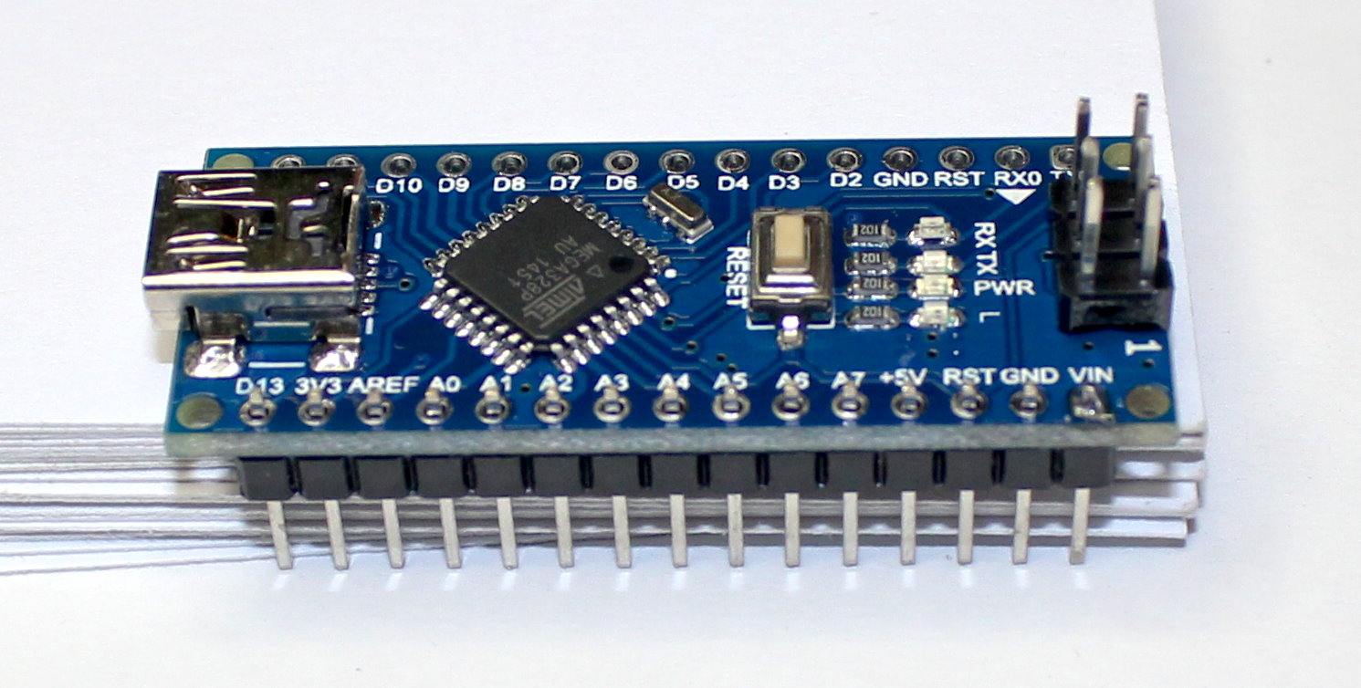
Next we turn the computer right-side-up and insert one of the 15 pin rows into the holes on the side of the computer board. Make sure the pins are only in the small holes, not in either of the larger mounting holes. Rest the board on a stack of paper to keep it nice and level. Now solder just the VIN pin (the pin on the right).
We solder only one pin so that we can easily fix any misadjustments in the angle of the pins. We need them to be perpendicular to the board in order for the pins to fit properly into the solderless breadboard. If the pins are not fully seated against the board, or are not nicely perpendicular, hold the board and pins in one hand while you melt the solder on the VIN pin. Now adjust the angle, and let the solder cool. Once you are happy with the angle, you can solder the remaining 14 pins onto the board.
Now do the remaining row of pins the same way.
If you happen to have a perfboard (a pre-made printed circuit board with regularly spaced holes (perforations) for soldering chips onto) there is an easier, sure-fire way to solder the pins in place while guaranteeing that they are aligned properly.
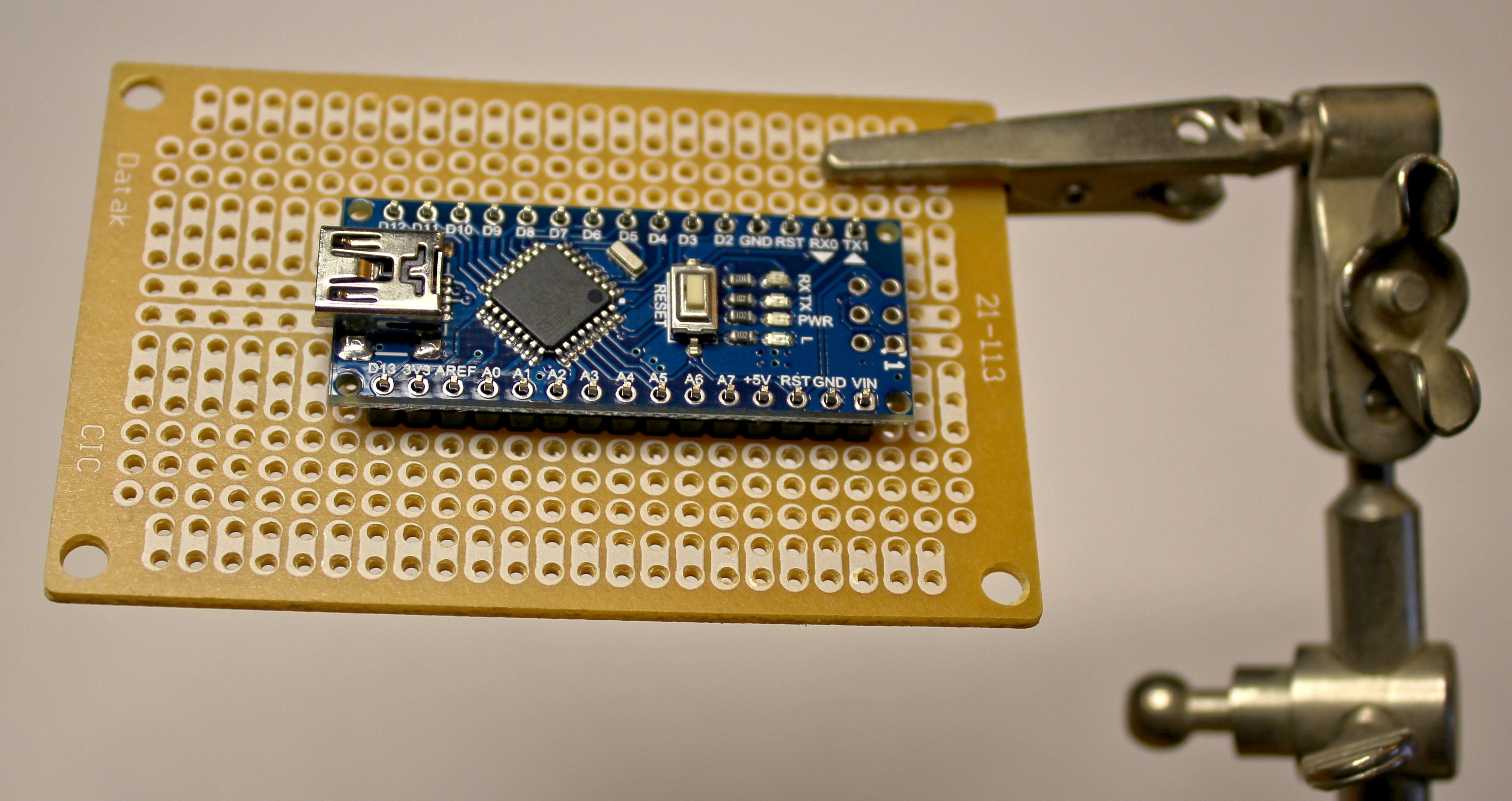
Place the header pins onto the tiny computer, and then let the long ends slip into the holes of the perfboard.
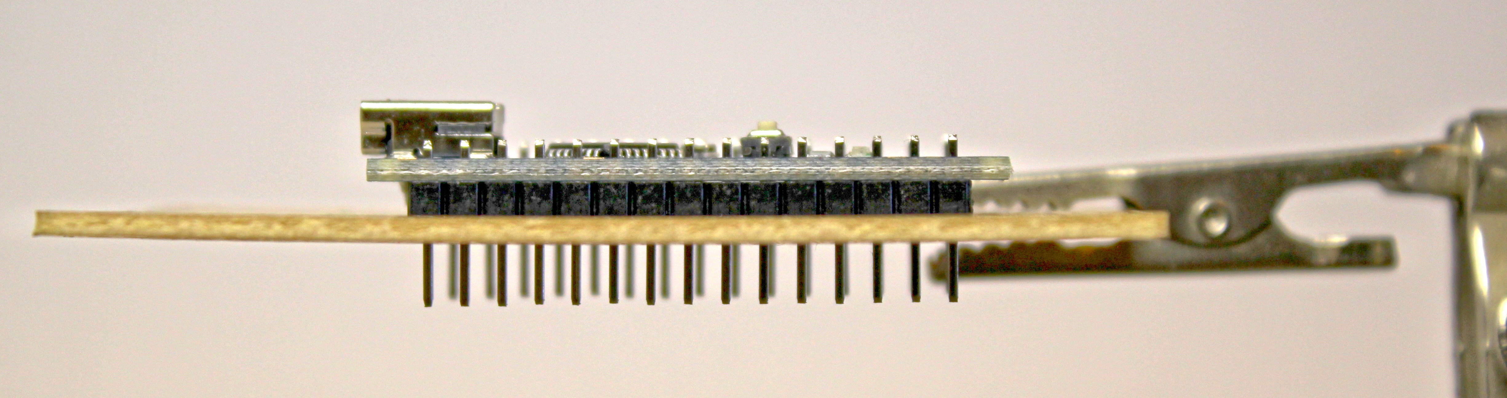
Now you can solder the pins, knowing the perfboard will keep them aligned, and gravity will keep them nicely seated.
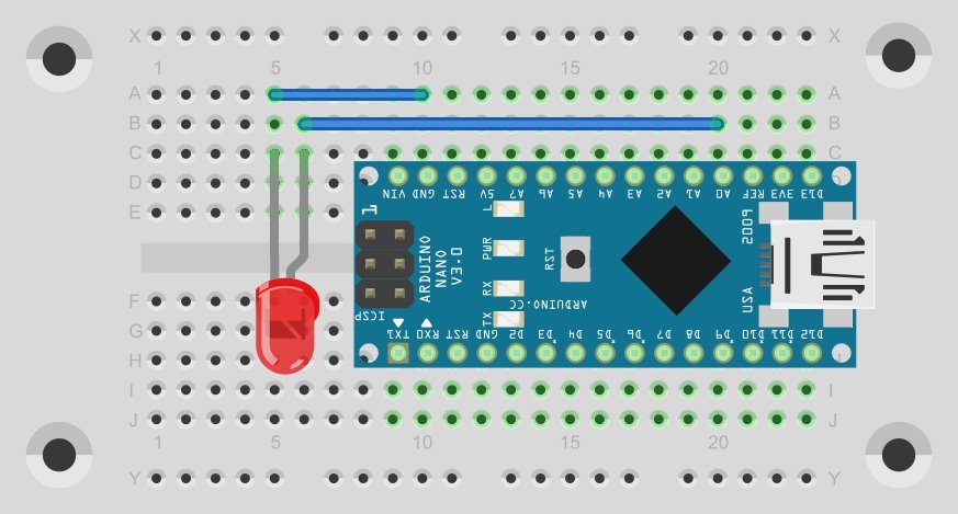
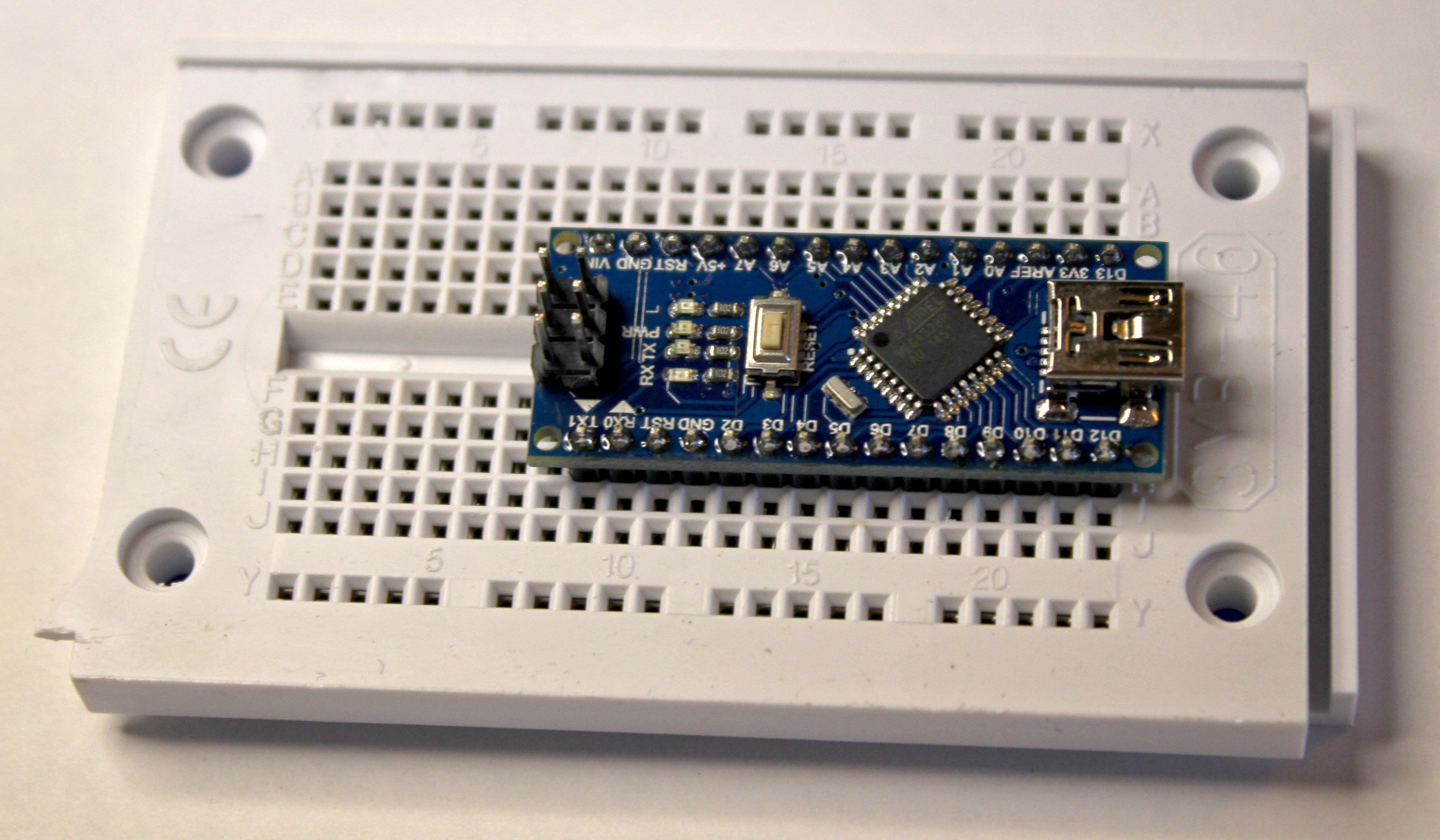
When the solder has cooled so you can handle the board without burning your fingers, you can insert it into the solderless breadboard. Be careful to only press on the pins, as it needs a bit of force to seat fully into the solderless breadbord, and you don't want to break anything. I like to put the board at the right side of the solderless breadboard, leaving room on the left for future circuits. That also helps keep the USB cable out of the way when we connect it.
Now let's measure something!
Use a wire to connect the pin labeled A0 to the pin labeled 5V. Just poke one end of the wire into a hole in the same column as the A0 pin, and poke the other end into a hole in the same column as the 5V pin. The A0 pin is one of the eight pins that can read analog voltages. The 5V pin is a pin that has 5 volts coming out of it.
Now we load the following tiny program into our tiny computer:
void
setup()
{
Serial.begin( 115200 );
}
void
loop()
{
Serial.println( analogRead( A0 ) );
delay( 1000 );
}
Run the program, and bring up the Serial Monitor window. If all went well, you should see the number 1023 printed every second.
Now remove the end of the wire from the 5V pin, and plug it into a hole in the same column as the GND pin. GND is short for "ground", which means zero volts. Now the number 0 should be printed every second.
The analogRead() function takes an argument of A0 to tell it which of the eight pins it is supposed to read. It returns a number from 0 to 1023, which represents the voltage it found on the pin. A zero means zero volts, and a 1023 means five volts.
Wouldn't it be nice if the program actually printed out the voltage? We can make it do that:
void
setup()
{
Serial.begin( 115200 );
}
void
loop()
{
Serial.println( 5.0 * analogRead( A0 ) / 1024 );
delay( 1000 );
}
The little program is now doing the arithmetic for us. It multiplies the reading by 5 (for five volts), and then divides that by 1024 (the number of steps the voltage can be read in). Now we see either 0.00 printing every second, or 5.00, depending on where the wire is plugged in.
But now we are losing some precision. We only see two decimal places (three significant figures), but we had four significant figures before. We can fix that. The println() method can take a second argument, separated from the first by a comma, that tells it how many decimal places to print. We'll tell it three, to get four significant digits:
Serial.println( 5.0 * analogRead( A0 ) / 1024, 3 );
Now the program prints out 4.995 or 0.000. We can see that the five volt pin is not quite five volts, but close enough.
Now we can pretty up our little program by wrapping it in a class and adding the word 'volts' to the output:
void
setup()
{
Serial.begin( 115200 );
}
class Voltage
{
enum { SENSOR_PIN = A0 };
public:
float
read( void )
{
return 5.0 * analogRead( SENSOR_PIN ) / 1024;
}
} voltage;
void
loop()
{
Serial.print( voltage.read(), 3 );
Serial.println( " volts" );
delay( 1000 );
}
Notice that the first print function doesn't say println. Without the 'ln' at the end, it does not end the line. This lets us add characters after the printed number, in this case the word "volts" with a space before the 'v'.
Notice on the board there is a pin labeled 3V3. This pin is for powering devices that require 3.3 volts instead of 5 volts. Plug the wire into a hole in the same column as that pin. When I do that, the program says 3.457 volts most of the time, but often some number slightly higher or lower. This pin is not regulated like the 5 volt pin, and it's value will fluctuate a bit.
Now let's measure a voltage that is not coming from the tiny computer. To do this, we need another wire. This wire will connect to the GND pin (poke it into a hole in the same column as the GND pin). Now we can connect the negative side of a small AAA battery to the GND wire, and the positive end of the battery to the A0 wire, and read the voltage.

When I did that, I got a reading of 1.655 volts.
Great, so now we have a battery tester, Is there anything more we can do?
You may be aware the light emitting diodes are also solar cells. If you shine a light on them, they produce electricity. We can use this feature to make a light sensor.
Connect the A0 wire to the anode of an LED. The anode is the long wire on the LED. I used a rectangular red LED. Connect the GND wire to the cathode of the LED. The cathode is the short wire on the LED.
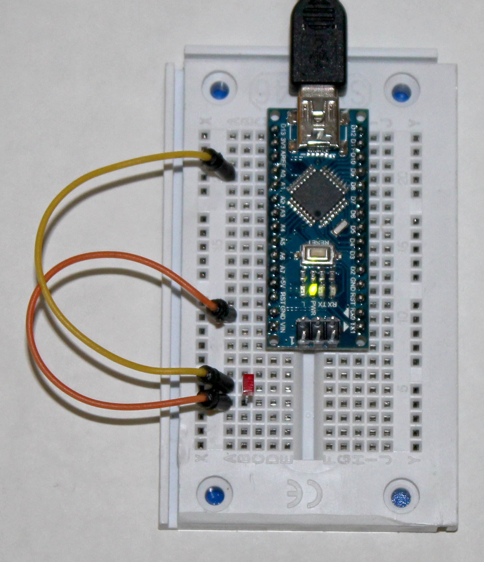
What does the voltage say? If it says 0.000, then you have the LED backwards, or you are doing this in the dark. In my dimly lit office, I get about half a volt. When I shine a flashlight on the LED, I get about 1.4 volts. When I put my hand over it to block the light, I can get all the way down to zero.
Some of our projects will be more complicated, and a photo will not be sufficient to figure out where all the connections are. For those situations, we will show a diagram, like the one below: