A sine wave generator is useful as a testing tool in electronics. We will use the one we build here later when we test another project. While we build this tool we will learn about two very handy parts to include in your other projects -- a thin film transistor liquid crystal display (color TFT LCD display) and a rotary encoder. With these we can create a menu system that lets the user control complex behavior with one very simple knob.
Here are the parts we will use for this project:
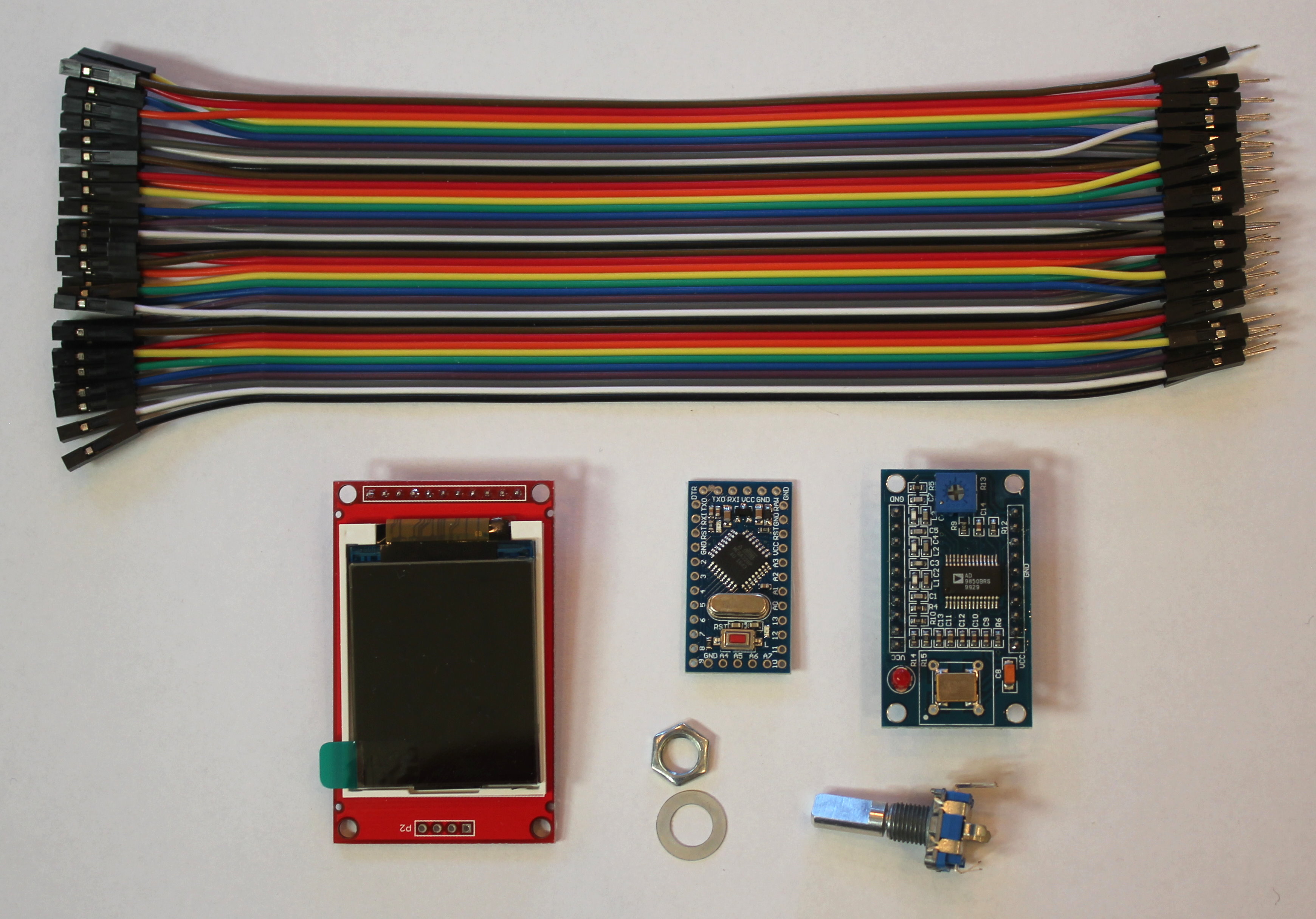
A kit containing all of these parts is available in our online store.
At the top of the image we have a Dupont ribbon cable. These have male and female connectors, and are very convenient for connecting parts with legs to breadboards or to other devices.
On the lower left in the photo is the TFT LCD display. This one is 1.8 inches in diagonal measure, and comes with a protective film over the screen that can be removed by pulling on the green tab. There are different versions of this display, and each version has a different color tab. When we use the library routines for driving the display, we will specify the green tag version.
At the lower right is a rotary encoder. This is a neat little device that lets our program know when the user pushes the knob down to select a menu item, or rotates the knob clockwise or counterclockwise to move over different menu items. In this first project, we will use it to select the frequency we want for our sine wave.
Above the rotary encode is the heart of the project, a Direct Digital Synthesis Sine Wave Generator board. This board uses the Analog Devices AD9850 chip to generate a sine wave of any frequency from 0 to 40 megahertz. We can use it to generate radio signals, test electronics parts, or make sounds.
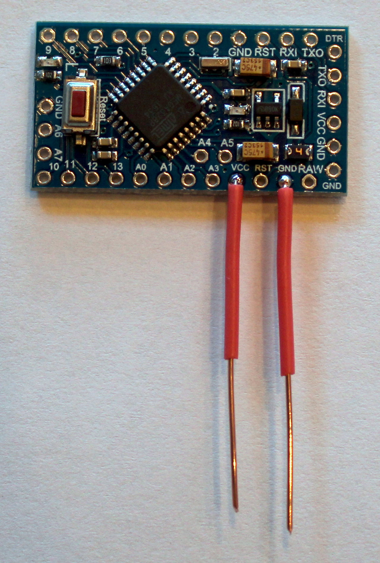
Lastly, we have our Arduino Pro Mini that will control all of the other devices. If you choose not to power this project from a battery, you can use an Arduino Nano instead of the Arduino ProMini, and power it from a USB hub, computer, or phone charger.
Since we will be connecting a battery, the LCD, the DDS board, and the rotary encoder to the Arduino's power and ground connections, we first add a couple of wires to the VCC and GND holes of the Arduino, so we can more easily connect several wires to those later.
Next, we plug the female ends of some ribbon cable to the pins on the LCD board. Three of those pins are not used (they are labeled NC on the board, for "No Connection"). We cut the male connectors off of the cable, since we will be stripping and soldering those ends directly onto the Arduino. If you like, you can just plug the male ends into the Arduino holes and solder them, but that makes the result a little bulkier.
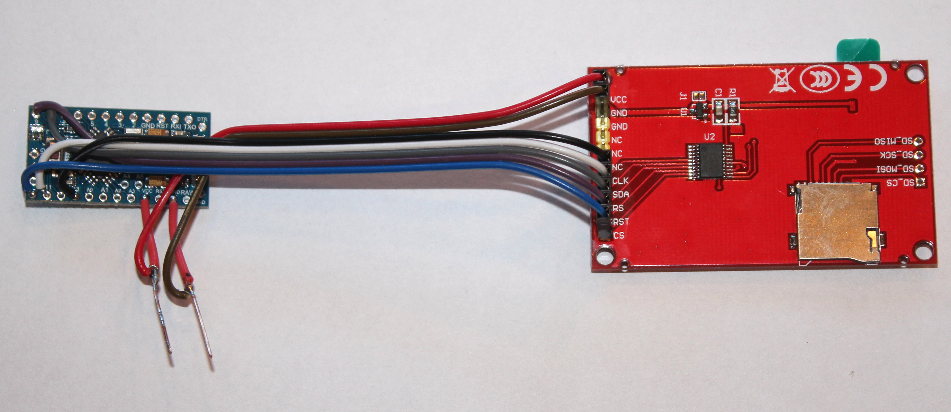 The pins labeled VCC and GND on the LCD board connect to the VCC and GND wires we soldered
to the Arduino. In the photo, they are the red and brown wires. Here is a closer view:
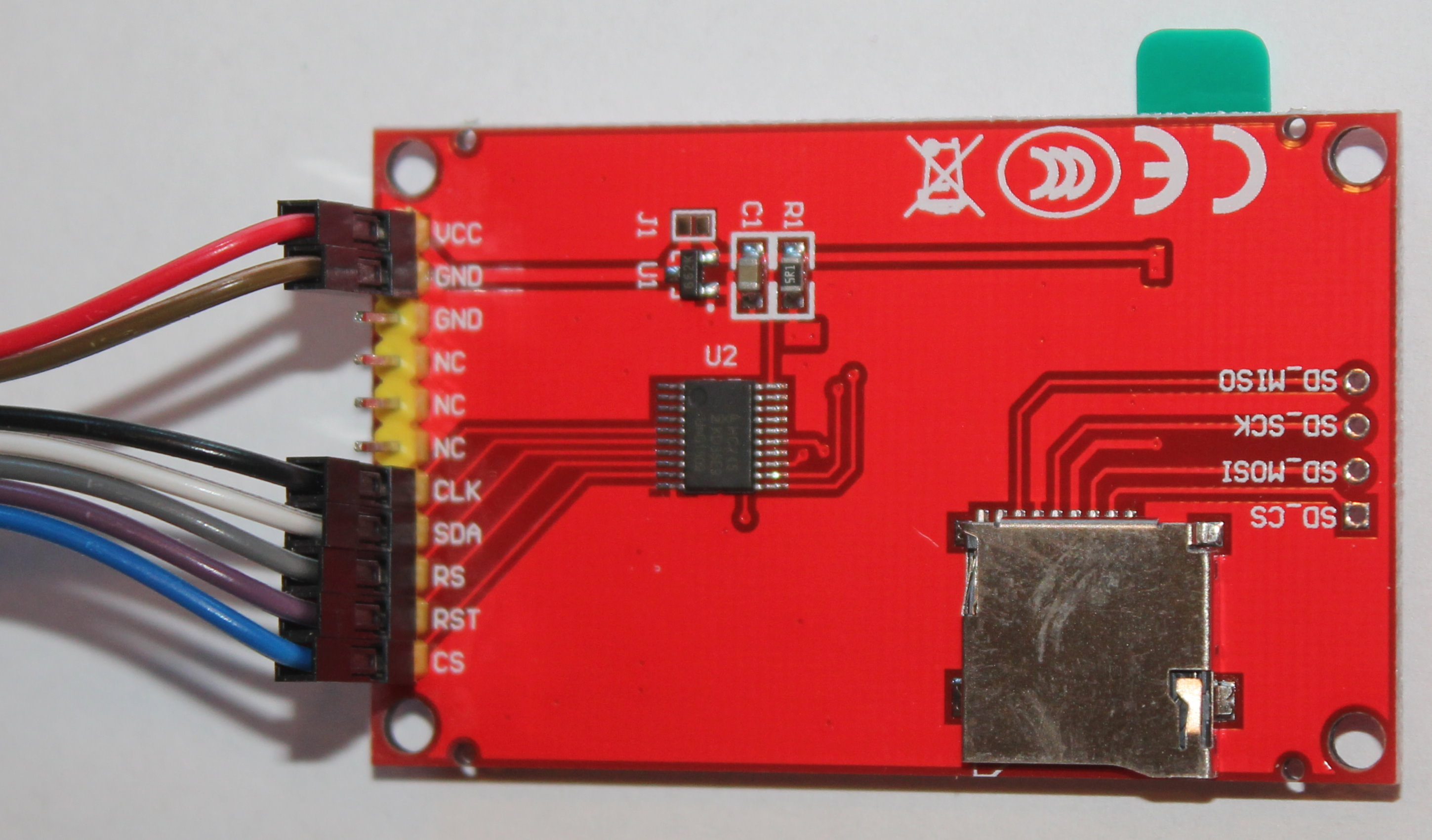
On the Arduino, the cable wires are soldered to the holes:
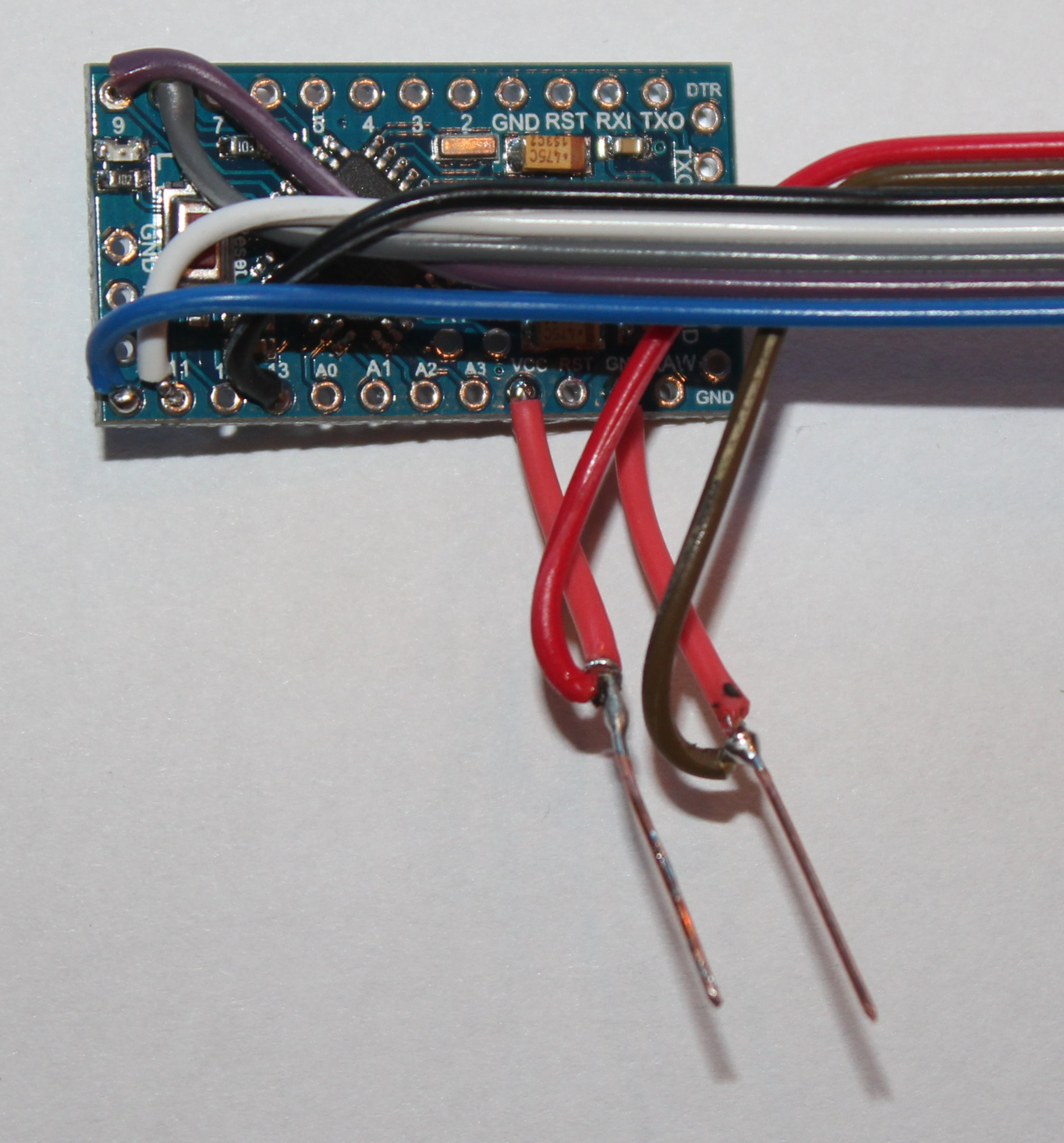
The wires are soldered to the Arduino pins as shown in the following table:
| LCD pin | Color | Arduino pin |
| VCC | Red | VCC |
| GND | Brown | GND |
| CLK | Black | 13 |
| SDA | White | 11 |
| RS | Gray | 8 |
| RST | Purple | 9 |
| CS | Blue | 10 |
Feel free to use other colors if you like. What is important is which pins on the LCD are connected to which holes in the Arduino.
Next we plug some more ribbon cable into the DDS board. Six wires will be in a row, and another two wires will be at the far left end, connected to ZOUT2 and GND. These last two are the output of the sine wave generator. The six wires in a row together let us control the DDS board.
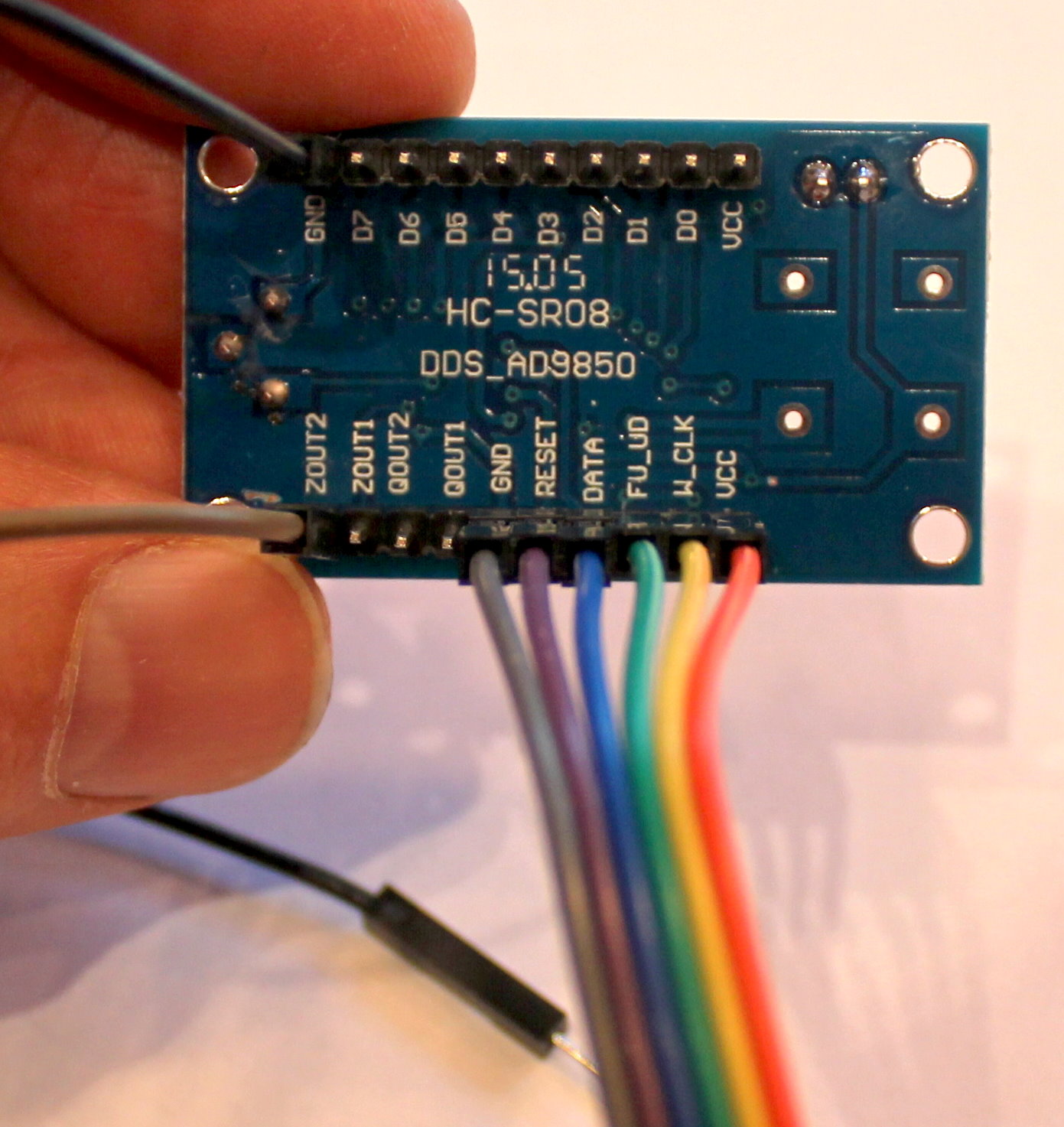
The VCC (orange) and GND (gray) wires at the outer ends of the six bundled wires connect to the Arduino VCC and GND pins.
The remaining four wires in that bundle connect to pins 7 through 4 on the Arduino, according to the following table:
| DDS board | Color | Arduino |
| VCC | Orange | VCC |
| GND | Gray | GND |
| W_CLK | Yellow | 7 |
| FU_UD | Green | 6 |
| DATA | Blue | 5 |
| RESET | Purple | 4 |
The next step is to prepare the rotary encoder. It has five pins -- two on one side for the push button switch, and three on the other side for the rotation sensor. Since one pin on the push button side will be connected to ground, and so will one pin from the rotation sensor, we will bridge those two pins at the rotary encode, so we only have four wires to solder to the Arduino.
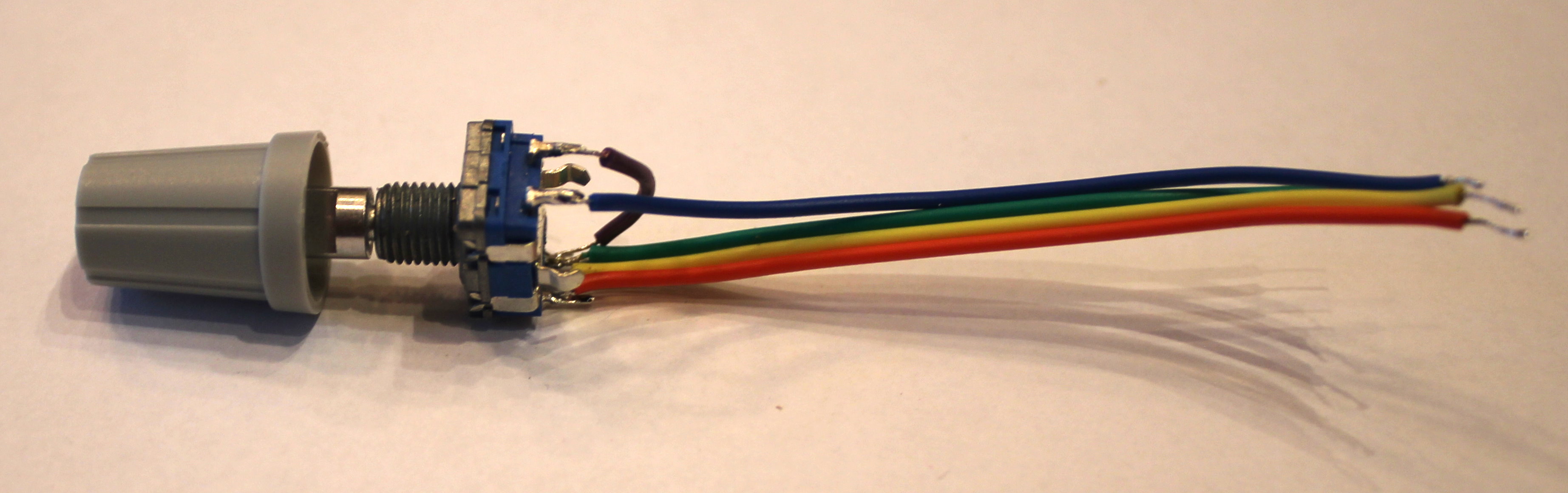
The photo above shows a purple wire connecting the ground pins together.
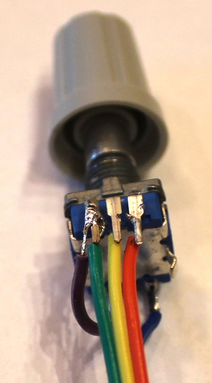
We attach a green wire to the left-most pin, which is the common pin. It will connect to ground on the Arduino. As the encoder is rotated, it will connect that pin to the yellow and orange wires in turn. If the yellow wire is grounded before the orange wire, the rotation is clockwise. If the orange wire is grounded before the yellow wire, the rotation is counterclockwise.
We connect the blue wire to the Arduino pin 3. Pushing the knob down will ground the blue wire, causing pine 3 to read as LOW, and we will know the user has pushed the button.
We connect the yellow and orange wires to the Arduino pins A2 and A3. These pins can be used as analog pins (hence the 'A' in their name), but we will be using them as ordinary digital pins to detect the rotation of the knob.
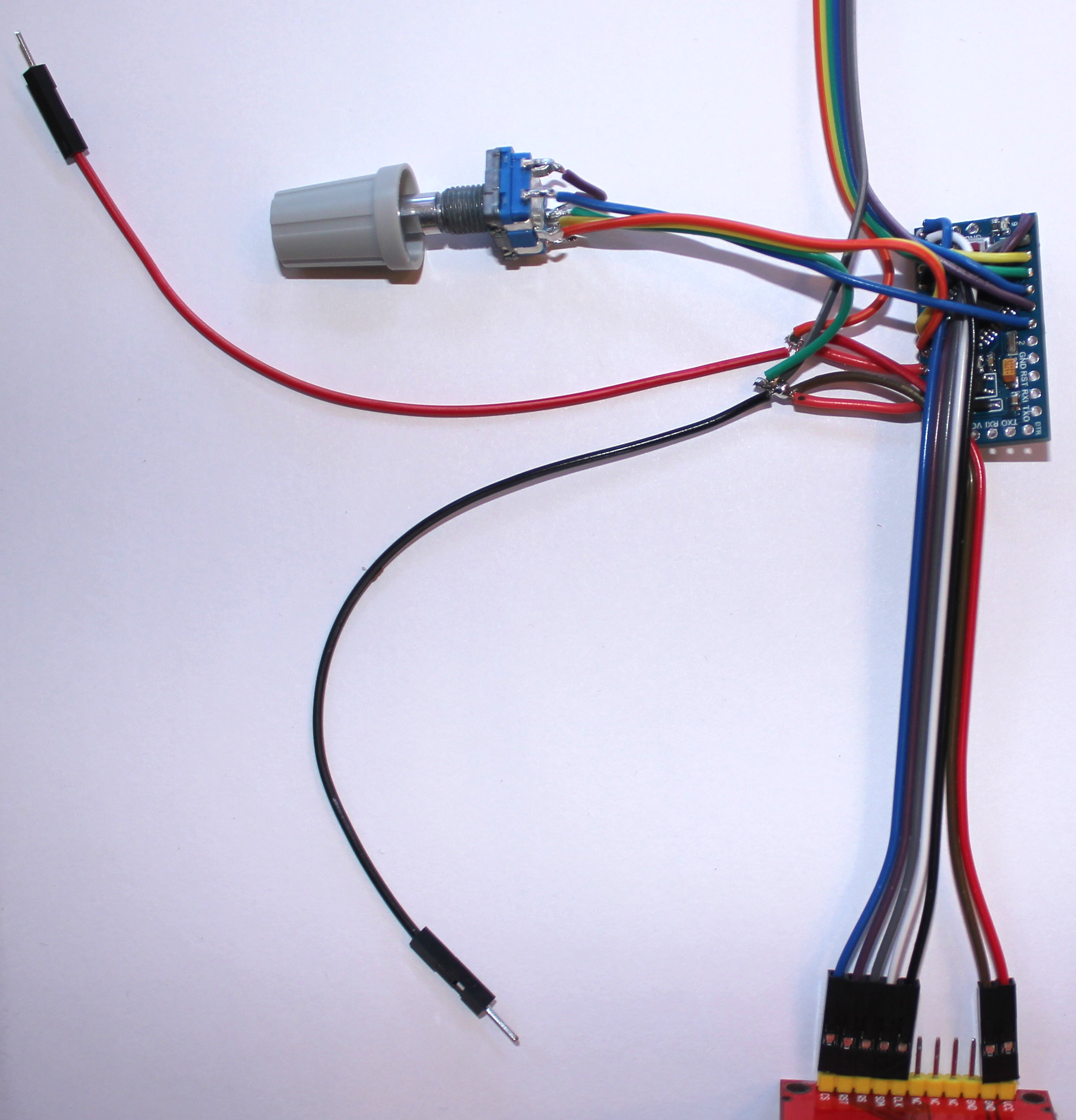
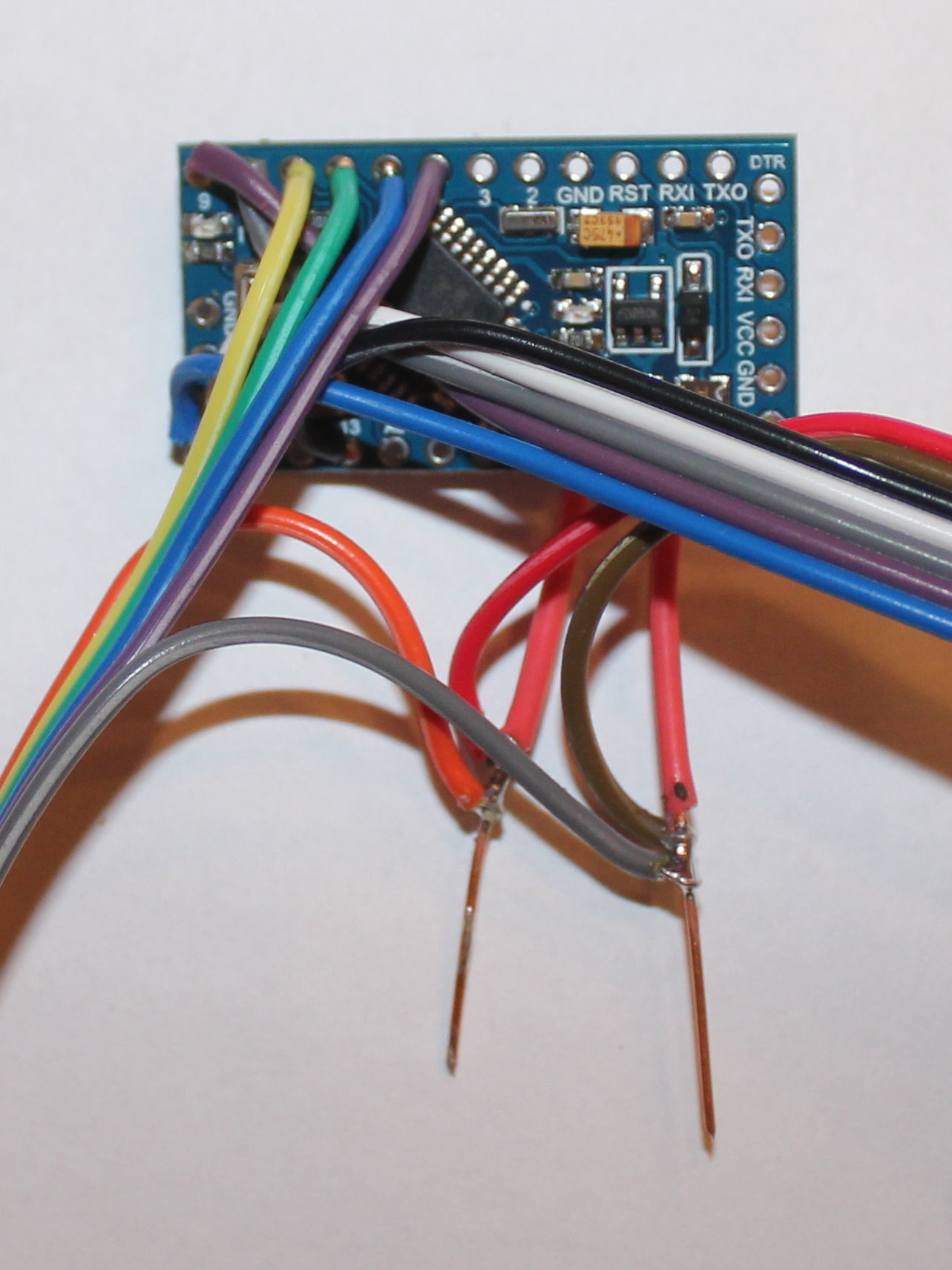
Lastly, we solder a black male Dupont connector to ground, and a red one to VCC. This will plug into our battery. It's a good thing we're done soldering, because our photo is beginning to look a little crowded. You can just see the orange and yellow wires from the rotary encoder connecting to A2 and A3 (right next to VCC), and the blue wire connecting to the hole marked 3.
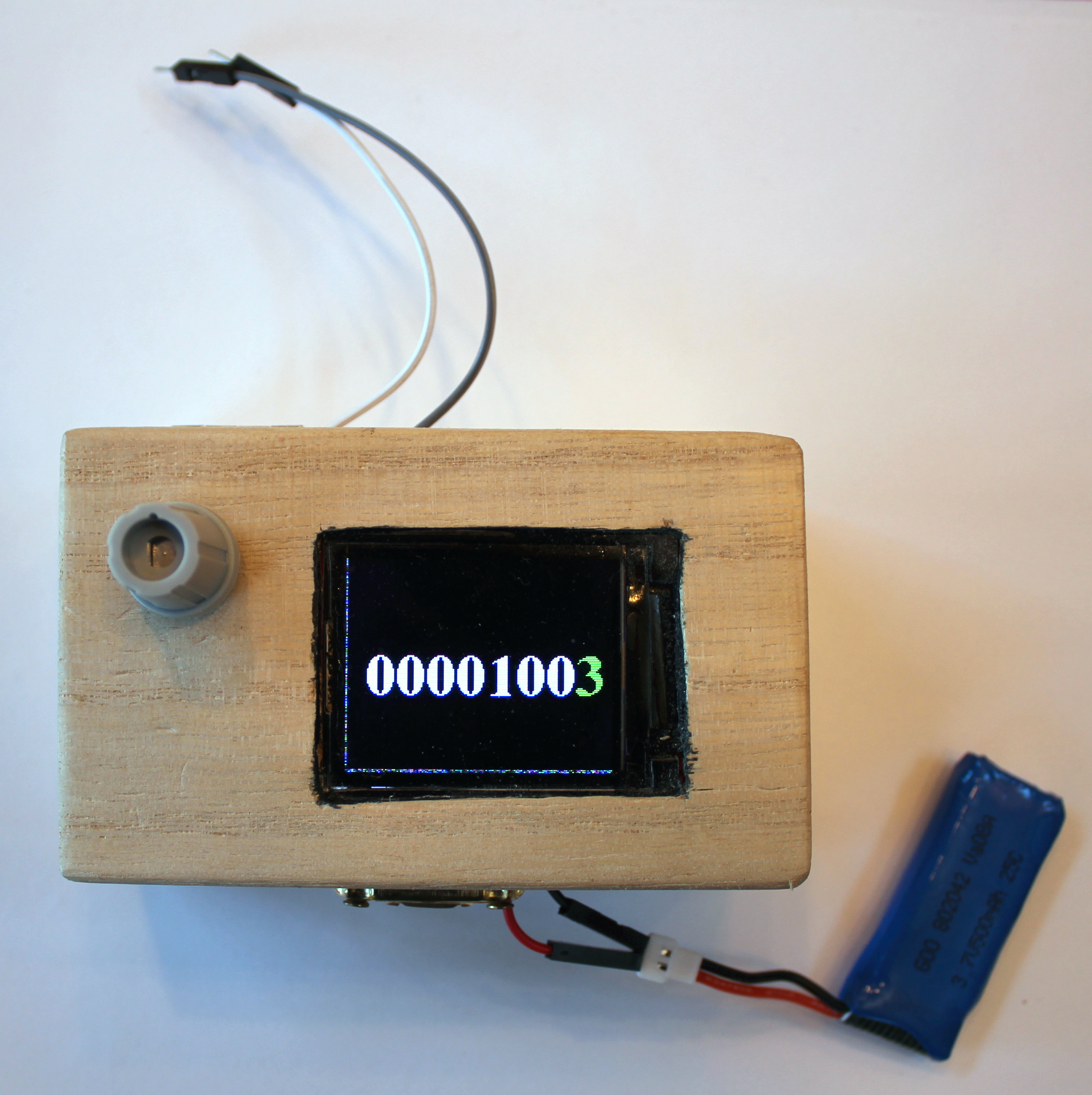
In the photo above, you can see it packaged in a small wooden box. Plastic boxes are probably even easier to work with. It is powered by a 3.7 volt lithium battery. I've let the battery hang out of the box for the photo, to show that the red and black wires have to match up.
The display shows is is putting out a sine wave at 1,003 Hertz.
To get it to work, of course, we need to add some software. The code for the signal generator itself is fairly short, due to the use of some convenient libraries:
# include <Arduino.h>
# include <EF_AD9850.h>
# include <Frequency.h>
enum { CLK = 7, FQUP = 6, RESET = 5, DATA = 4 };
EF_AD9850 AD9850( CLK, FQUP, RESET, DATA );
enum { TFT_CS = 10, TFT_RST = 9, TFT_DC = 8 };
Adafruit_ST7735 tft = Adafruit_ST7735( TFT_CS, TFT_DC, TFT_RST );
Frequency freq( 3, A2, A3, tft );
ISR( PCINT1_vect )
{
freq.rotated();
}
ISR( PCINT2_vect )
{
freq.pushed();
}
void
setup( void )
{
freq.init();
freq.value( 1000 );
freq.show_frequency();
AD9850.reset();
AD9850.wr_serial( 0, freq.value() );
}
unsigned long int old_freq = 0;
void loop( void )
{
if( freq.value() != old_freq )
{
AD9850.wr_serial( 0, freq.value() );
old_freq = freq.value();
}
}
Looking at the code from the bottom up, we have our loop() routine, which checks to see if the user has changed the frequency. If so, we call the wr_serial() routine of the AD9850 object to tell our DDS frequency synthesizer board to change its frequency. Then we remember the frequency so we can check for any changes.
The setup routine is also simple. It initializes the freq object, sets its value to 1000 Hertz, and calls show_frequency() to display it. Then it resets the AD9850 object that controls the DDS board, and sets its frequency to match what is shown on the LCD display.
Above the setup() routine are two interrupt routines. These will be called automatically if the pins they are connected to change from LOW to HIGH or HIGH to LOW. The top routine is controlled by changes on pins A2 and A3. The lower routine is controlled by changes on pin 3. Thus when the rotary encoder is rotated, the freq object's rotated() method is called, and when the knob is pushed down, the freq object's pushed() method is called.
Finally, we reach the declarations at the beginning of the program. We are using the EF_AD9850 library to control the DDS board. We construct the AD9850 object, telling it which Arduino pins are connected to the board.
Likewise, we are using the Adafruit ST7735 library to control the thin-film transistor liquid crystal display (TFT_LCD). We construct the tft object, telling it which Arduino pins are connected to it.
The freq object uses a library called Frequency, which I will describe in detail in a moment. This is a helper library that manages the rotary encoder and the TFT_LCD display to allow the user to select the frequency of the sine wave we are generating.
Installing Libraries
The Arduino IDE makes it easy to install and use libraries (packaged program files that perform specific tasks).
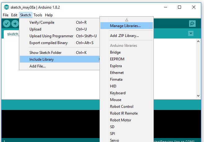
The Sketch menu has an item called Include Library. In that sub-menu there is an item called "Manage Libraries...".
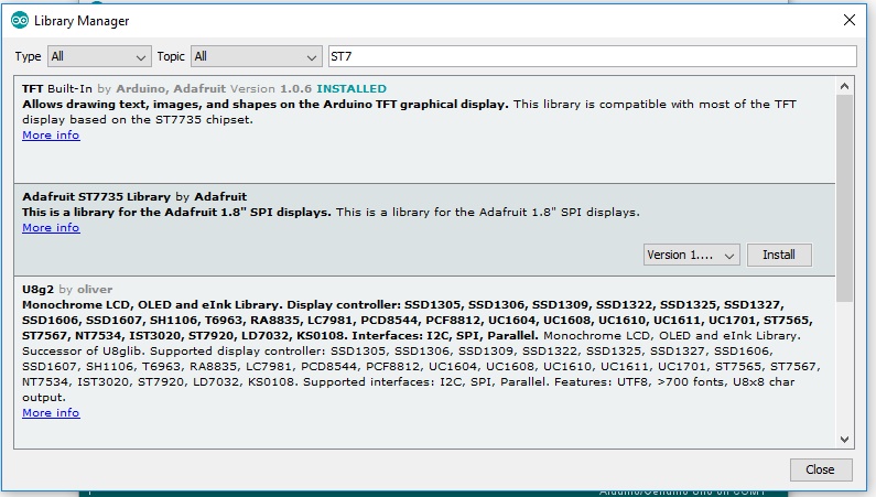
This pops up the Library Manager dialog box. If we type in ST7735 in the Search box at the top of the dialog, we will see that the library manager already knows about the Adafruit library for that device. You have to click on the result in order for the "Install" button to show up (I have no idea why they did that -- it would be much more intuitive if it were visible right away).
Click on Install, and the library will become available to the IDE. You will also need to install the Adafruit GFX library the same way. The GFX library contains generalized code for fonts and line drawing.
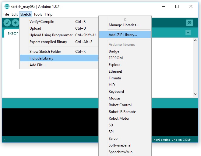
While the Library Manager has a lot of libraries, there are even more libraries out on the Internet that it does not know about. So there is another simple way to add libraries to the IDE. We can tell it to get a library from a ZIP file on our local disk.
The Frequency library is one I wrote for this book, so the Arduino Library Manager doesn't know about it. Just click on the link (here it is again) and it will download onto your computer.
The AD9850 library is available from ElecFreaks, I made two slight changes to their code, removing the two unnecessary include files from their header file. You can click on that link for the most up-to-date version (and make those modifications yourself), or click on the copy I have here.
From the Sketch menu, select the sub-menu Include Library, and then select the item "Add .ZIP Library...".
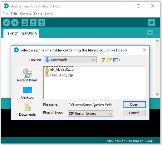
That will bring up a dialog box asking for the location of the .ZIP file you just downloaded. Select the file, and it will be added to the Library Manager. Do this for both Frequency.zip and for EF_AD9850_library.zip.
Now that we have all the libraries loaded, we can paste in the file and it will compile and download onto the Arduino.
For convenience, I have created yet another library. This one has all of the other libraries inside it. So you can simply download the SineWaveGenerator.zip file, and use the Library Manager to add it as a .ZIP file. Then the examples in the library will be available in the Arduino IDE. In the IDE menu, go to:
- File
- Examples
- SineWaveGenerator
- Examples
and click on SineWaveGenerator to run the example.
When the program has compiled and loaded, it will start putting out a beautiful sine wave on the two output wires. You can listen to it on headphones, or view it on an oscilloscope. Don't have an oscilloscope? You're in luck -- building an Arduino oscilloscope is our next project!