Switching a light on and off is quite useful, but often we want more. We want to control the brightness of the light, or control how much power is delivered to a heater.
To make a dimmer circuit, we start with our basic AC light switch circuit, and then we add a part that will tell us when the AC current crosses zero volts (this is called, surprisingly, a zero crossing circuit).
The parts arrangement on the board starts out looking just like the light switch circuit:

The two changes we have made so far are replacing the BT136 triac with one that can handle more power (the Q6012LH1), and replacing the 100 ohm 1/4 watt resistor with a 150 ohm 1/2 watt resistor. We do this because we want to control high power loads, such as a 700 watt electric rice cooker, instead of just a low wattage light bulb. The 1/2 watt resistor is a good deal larger than the 1/4 watt resistor we used before, and its leads have to be bent under the resistor in order to fit into the right holes. In the photo it might be a little hard to see, but the resistor connects pin 4 of the MOC3012 to the middle pin of the triac, just like in the previous circuit.
Next we will add the zero crossing circuit. It is made from a special optoisolator (the PC814), and a pair of 4700 ohm resistors:

Pin 1 of the PC814 is marked with a dark circle, and is on the upper right in the photo. One 4700 ohm resistor connect pin 1 to the middle pin of the triac. The other 4700 ohm resistor connects pin 2 to one side of the AC power supply. This will be easier to see when we turn the board over.

We have put the board into a wooden box. The lid of the box carries a standard duplex wall socket, with its two receptacles for plugging in appliances or lamps. A three-prong cord is fed through a hole in the box. The green ground wire is connected to the duplex socket's ground (middle pin). The black "hot" wire is soldered to the board where the second 4700 ohm resistor connects it to the PC814. Another wire connects the black "hot" wire to the duplex socket. The middle pin of the triac is connected to the remaining (neutral) side of the duplex socket. Finally, the white "neutral" wire from the cord is soldered to the other output pin of the triac (the right pin in this photo, since the board is upside-down, but that is the left pin when the board is right-side-up).

The schematic for the circuit looks like this:
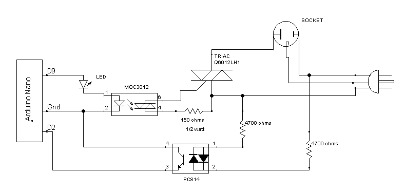
The PC814 has two LEDs inside. That way, no matter which way the AC current flows, one LED or the other will be lit. They will only both be dark if the current is zero. This is how the tiny computer will know when the AC current has crossed zero. We use a pair of 4700 ohm resistors to drop the AC current down to a level low enough to light the LEDs without blowing them up.
We care about when it crosses zero because that is how we will control how much power we deliver to the load (which may be a lamp, or our rice cooker).
The tiny computer waits until the AC current is zero. This happens 120 times each second. When the computer sees a zero crossing, it starts a countdown timer. When the timer counts down to zero, the computer turns on pin D9. This lights up the LED, and the little LED inside the MOC3012, turning on the power.
Since the tiny computer waited before turning on the power, the first part of the AC sine wave was skipped. This means that less power was delivered. The longer the delay, the less power goes to the load.
Delay: 0Power: 0%
You can see how the delay affects the power level by moving the slider from left to right in the image above.
The longer we delay before turning on the switch, the less of the AC sine wave remains to power the device (the lamp or the rice cooker).
We can combine the light dimmer code with the PID controller code from the earlier chapter, and make a PID controlled rice cooker. We use a temperature sensor like we did before, but instead of using analogWrite() to control the current to the heater, we use our new code for controlling AC current.
In this project, we are going to use our cheap $20 rice cooker to keep a pot of water at exactly 133 degrees Fahrenheit. That is the ideal temperature for a medium rare steak. If we briefly sear the sides of the cold steak on a very hot skillet, we can get a nice brown outside while the inside of the steak stays cold. Then we put the steak in a plastic Zip-Loc bag, squeeze the air out of the bag so it will sink, and zip it closed. The bag goes into the water bath for 45 minutes. The result is a perfect steak, cooked medium-rare all the way through, with no overdone parts on the outside, and no underdone parts on the inside.
The code is here.
The PID controller part is the same as before. We use pin 3 for the temperature sensor. We use pin 9 to turn the heater on and off. We use pin 2 as an input to tell us when the AC current crosses zero.
The three tiny subroutines that are the heart of the AC current control are shown below. The zeroCrossingInterrupt() routine is called whenever the AC current crosses zero. All it has to do is start the timer. The strange words starting in TC are some timer control registers that we set to 4 and zero. That tells the timer in the tiny computer to divide the 16 megahertz clock by 256, and then start the timer running.
void
zeroCrossingInterrupt()
{
  TCCR1B = 0x04;       // start timer with divide by 256 input
  TCNT1 = 0;           // reset timer - count from zero
}

ISR(TIMER1_COMPA_vect)
{
  digitalWrite( heater, HIGH );  // set triac gate high
  TCNT1 = 65536 - PULSE;       // trigger pulse width
}

ISR(TIMER1_OVF_vect)
{
  digitalWrite( heater, LOW ); // turn off triac gate
  TCCR1B = 0;               // stop unintended triggers
}
The other two very strange looking subroutines are timer interrupt routines. The first one is called when the timer reaches our delay count. It turns on the triac, so the heater starts heating the water. It sets the timer for a very short delay (4 ticks of the clock) which is enough to turn on the triac. The triac will stay on until the AC current crosses zero (that's how triacs work). After those 4 clock ticks, the last interrupt routine gets called, because the timer overflowed (the 4 ticks counted down to zero). We turn off the triac trigger (the triac will stay on anyway, until the AC current crosses zero). We won't cover the gory details of all the clock registers and what they mean. That is covered in exhausting detail in the ATMega328 programming guide.